A mobile concrete batching plant

A technology of batching equipment and concrete, which is applied to batching batching instruments, batching weighing instruments, clay preparation devices, etc., can solve the problems of extra cost of batching equipment, elevation, and hindering the transportation of batching equipment.

Inactive Publication Date: 2010-03-31
约翰逊·李·吴
0 Cites 5 Cited by

AI-Extracted Technical Summary

Problems solved by technology

[0004] 1. Requires installation time before operation can start in the field
[0005] 2. Additional costs will be incurred for the installation of the batching equipment
[0006] 3. The use of passive loading, especially in the loading of aggregate material (which needs to be preloaded), greatly hinders the transportation of batching equipment to the construction site
[0008] 5. The water is obtained from the con...

Method used

[0043] According to the present invention, the sloped bottom wall 14a allows for convenient and efficient transfer of cement material to the cement outlet 14c and to the conveyor 28. Furthermore, the present cement silo 14 is characterized in that it holds a large volume equivalent to a total volume of at least 1400 bags of cement material, which is at least twice the volumetric capacity of existing mobile concrete batching equipment. As further shown in FIG. 7 , the water supply tank 13 is formed by an inclined upper wall 13 c , a vertical wall 13 d and a horizontal wall 13 e , and a water pump W is installed from the water and connected to the water supply tank 13 . In addition, the outer shape of the water supply tank 13 , specifically, the inclined upper wall 13 c coincides with the inclination of the bottom wall 14 a to define the inclined space 15 . The corresponding shape and alternate arrangement of the cement silos 14 and water tanks 13 saves space and provides balance and counterweight to the entire batching plant.
[0058] Before the mobile concrete batching equipment 10 of the present invention is transported to the construction site, the water supply tank 13 and the cement silo 14 are first preloaded according to the aforementioned procedure. The transport device is fastened to the chassis 12 at the rear of the dosing plant 10 . In operation, the main frame suppo...

Abstract

The present invention relates to a mobile concrete batching plant comprising a main frame supporting assembly being detachably connected to a transport means; a water tank being supported at the lowerrearward portion of said main frame supporting assembly, a cement silo being supported at the upper rearward portion of said main frame supporting assembly and spacedly disposed on top of said watertank, a 'cement weigh batcher and a suspended aggregate weigh batcher being supported at the forward portion of said main frame supporting assembly, means to convey cement material from said cement silo into said cement weigh batcher, weight controlling means being operationally connected to said cement weigh batcher and said aggregate weigh batcher, and distribution means to convey and batched feed cement materials, aggregates and water to a material mixing means to constitute a proportionate concrete mix.

Application Domain

Mixing operation control apparatusIngredients proportioning apparatus +2

Technology Topic

Water tanksConstruction aggregate +2

Image

  • A mobile concrete batching plant
  • A mobile concrete batching plant
  • A mobile concrete batching plant

Examples

  • Experimental program(1)

Example Embodiment

[0034] Before describing the preferred embodiments of the present invention in detail, it should be understood that the terms and terms used herein are only for illustrative purposes and should not be regarded as limiting.
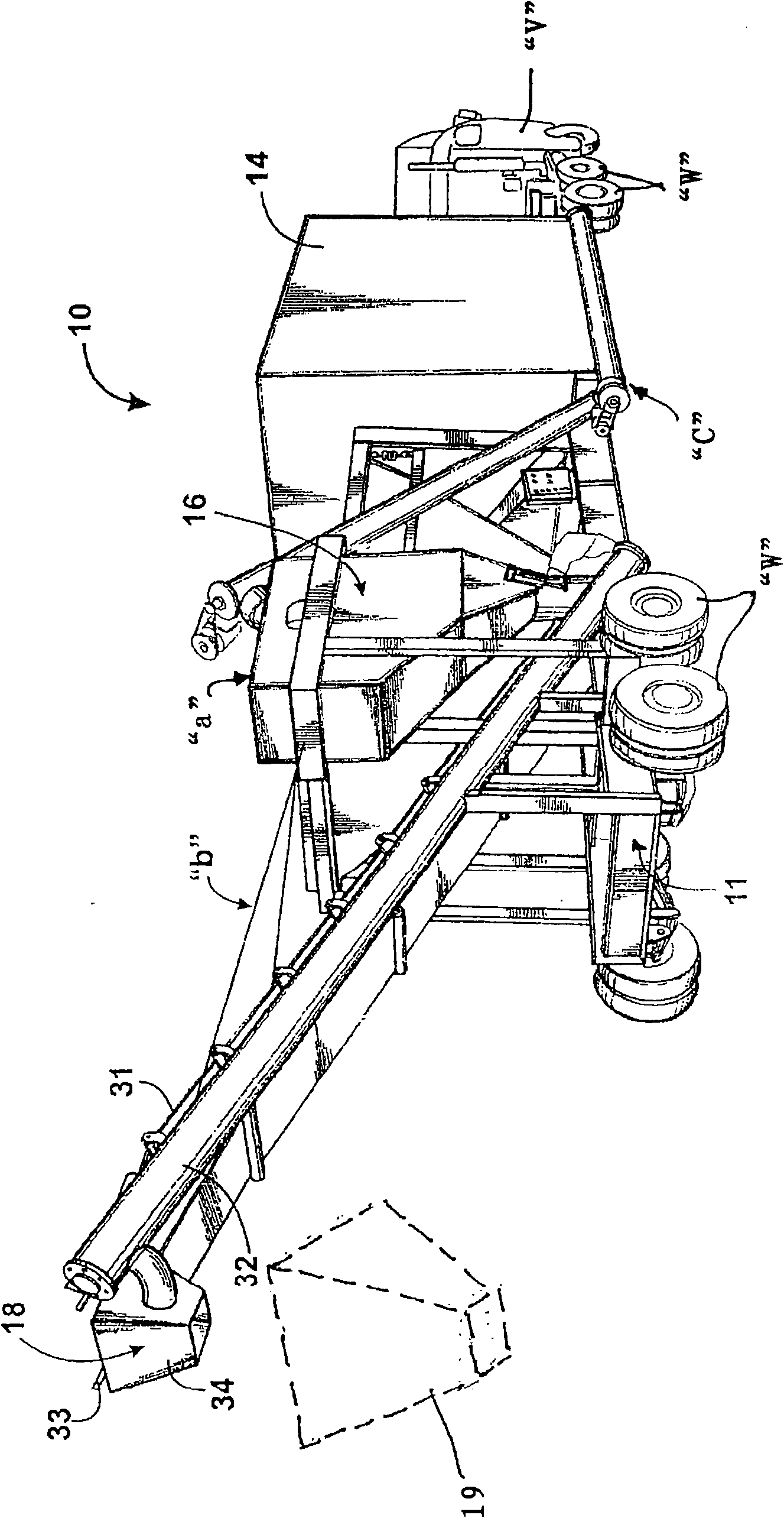
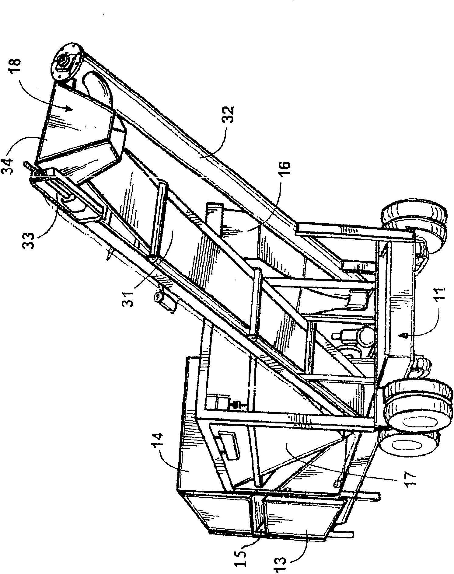
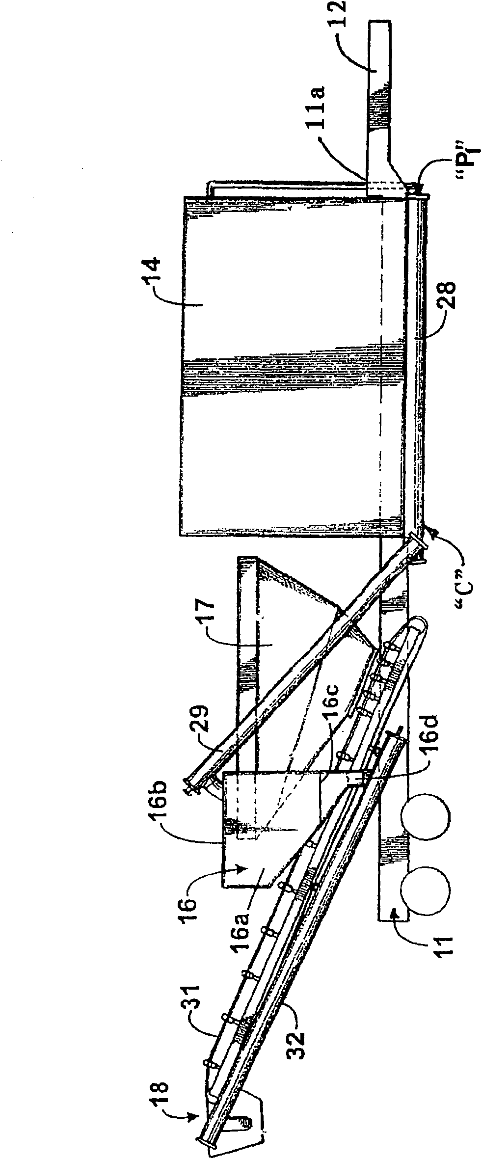
[0035] Referring now to the different views of the drawings, the same reference numerals in these drawings denote the steps, parts or elements in the description that can be implemented below, showing the overall reference 10 for the mobile concrete batching plant invention.
[0036] Now specifically refer to the Figure 1-5 , The mobile concrete batching plant 10 according to the present invention includes: a main frame support assembly 11, which has a chassis 12 provided at its rear end portion 11a and detachably connected to the transport device "V", and is preferably supported on the main frame A transportation wheel W provided at the front of the assembly 11; a water supply tank 13 supported at the lower rear of the main frame support assembly 11; and a water supply tank 13 supported at the rear of the main frame support assembly 11 and spaced apart by spaces 15 Above the cement silo 14.
[0037] The mobile concrete batching equipment 10 also includes a cement weight batcher "a" supported on the front of the main frame support assembly 11, a device "C" that transfers cement materials from the cement silo 14 to the cement weight batcher 16, and The suspension mode also supports the aggregate weight batcher 17 arranged in front of the main frame support assembly 11 and adjacent to the cement weight batcher 16.
[0038] Furthermore, Figure 1-5 The present invention shown herein for the mobile concrete batching plant 10 also includes a distribution device 18 provided at the front end part "b" of the mobile concrete batching plant 10, and the distribution device 18 is used for distributing the prepared cement material and bone The material and water are conveyed and supplied to the material mixing device 19 to form a proportional concrete mixture. Preferably, the material mixing device 19 may be a transport vehicle 19a loaded with a mixer or a rigid structure 19b loaded with a mixer.
[0039] In order to control and provide a measurement index about the weight/volume of the cement material actively loaded on the cement weight batcher 16, a weight-volume control device 20 (see Figure 12b ) Is arranged on the main frame support assembly 11 and is operatively connected to the cement weight batcher 16. Similarly, the weight/volume of the aggregate material is also controlled and measured by the weight-volume control device 20 which is also operatively connected to the aggregate weight batcher 17, which is preferably also actively loaded to the bone Mix the gravel and sand in a suitable and proper proportion of the material weight batcher 17.
[0040] In addition, according to the present invention, both the cement weight batcher 16 and the aggregate weight batcher 17 are provided with a weighing indicator device 21, which is arranged on the outer surface part to facilitate instant observation of the number. And is electrically connected to the weight-volume control device 20. For example, such as Picture 9 As shown, the weighing indicator device 21 for the aggregate weight batcher 17 includes a main frame 21a, an LCD 21b supported on the main frame 21a and preferably supported on the aggregate weight batcher 17 by an attachment device 21c .
[0041] Refer to the attached Figure 4 , 6 And 7, the water supply tank 13 has a substantially triangular shape and extends in the longitudinal direction of the lower rear part of the main frame support assembly 11. In addition, the water supply tank 13 occupies more than half of the total area of ​​the lower rear part of the main frame support assembly 11, and is provided with Image 6 with 7 The water inlet 13a and outlet 13b are shown.
[0042] Refer again Figure 7 , A novel and creative feature of the present invention relates to the shape of the cement silo 14 and the water supply tank 13 and the orientation of the cement silo 14 relative to the water supply tank 13, thereby between the water supply tank 13 and the cement silo 14 The space 15 formed is inclined. More specifically, the cement silo 14 occupies the entire area of ​​the lower rear portion 11 b of the main frame support assembly 11 adjacent to the water supply tank 13. Secondly, the cement silo 14 has a downwardly inclined bottom wall 14a extending from the shortened side wall 14b to one side wall 14c of the cement silo 14. The cement outlet 14d is formed at the lower part of the side wall 14c and the bottom wall 14a, and directly communicates with the conveyor 28 connected to each other. An upper wall 14e is also formed to completely define the structure of the cement silo of the present invention.
[0043] According to the present invention, the inclined bottom wall 14a allows the cement material to be conveniently and efficiently transferred to the cement outlet 14c and to the conveyor 28. In addition, the present cement silo 14 is characterized in that it contains a large volume equivalent to the total volume of at least 1400 bags of cement materials, which is at least twice the volume capacity of the existing mobile concrete batching equipment. Such as Figure 7 As further shown, the water supply tank 13 is formed by an inclined upper wall 13c, a vertical wall 13d, and a horizontal wall 13e, and the water pump W is installed from the water and connected to the water supply tank 13. In addition, the outer shape of the water supply tank 13, specifically, the inclination of the inclined upper wall 13 c and the bottom wall 14 a coincide to define an inclined space 15. The corresponding shapes and alternate arrangements of the cement silo 14 and the water tank 13 save space and provide balance and counterweight for the entire batching equipment.
[0044] Refer again Image 6 , The cement silo 14 is provided with a cement loading pipe 22 and a cement vent pipe 23 at its rear. The loading of the cement material to the cement silo 14 is carried out by air-loading the cement material through the inlet portion 22a of the cement loading inlet pipe 22, in which the cement material is transferred to the cement silo 14, At the same time, the duct breather 23 serves as a pressure release port when the aerodynamic force starts.
[0045] Another example Image 6 As further shown in, a water hose 24 is provided at the water inlet 13a so as to load water into the water supply tank 13 before transporting the batching equipment 10 to the construction site.
[0046] Refer to the drawings again, specifically figure 1 with image 3 , The weight batcher 16 arranged and supported at the front end "a" of the main frame support assembly 11 includes: a cement hopper 16a, the cement hopper 16a has an open upper portion and a bottom portion 16b and 16c; and a bottom cover 16d directly connected with the open bottom 16c; And an actuator "A" that controls the opening and closing actions of the bottom cover 16d. The actuation device "A" is electrically connected to the main control panel "P" provided on the main frame support assembly 11 (the weight-volume control device 20 is also arranged and positioned here), such as Figure 8 Shown.
[0047] And similarly, as Figure 4 , 9 As shown in and 10, the aggregate weight batcher 17 according to the present invention is also directly adjacent to the cement weight batcher 16 and is supported at the front "a" of the main frame support assembly 11. reference Figure 4 The aggregate weight batcher 17 includes: an aggregate hopper 17a having an open upper portion 17b and a bottom portion 17c; a bottom cover 17d communicating with the open bottom portion 17c; and a device that controls the opening and closing actions of the bottom cover 17d Actuation device "A". The actuation device "A" is electrically connected to the main control panel "P" provided on the main frame support assembly 11 (the weight-volume control device 20 is also arranged and positioned here), such as Picture 11 with 11 shown in a.
[0048] Although existing types of conventional actuation devices and equipment known to those skilled in the art can be used to activate the actions of the bottom covers 16d and 17d, it is preferable to control the bottom cover 16d of the cement weight batcher 16 and the aggregate weight. The actuating device "A" of the opening and closing action of the bottom cover 17d of the dispenser 17 is a pneumatic actuator that is easily controlled by the main control panel P.
[0049] According to Picture 9 As shown in the present invention, the aggregate weight batcher 17 is suspended relative to the main frame support assembly 11 by a suspension device 25, which is located at the upper edge 17e of the aggregate hopper 17a and at the main frame support assembly 11. The support column members 11a provided on the front portion "a" are arranged and further connected to each other. At least four (4) suspension devices 25 are provided at each corner of the main frame support assembly 11 through the support column members 11a provided on the main frame support assembly.
[0050] Refer again Picture 9 , The suspension device 25 includes a sensing device 26 suspended and supported by a pair of opposed hooks 27a and 27b, the hooks 27a and 27b at the upper edge 17e of the aggregate hopper 17a and at the front of the main frame support assembly 11 "a ”Is installed on the support column member 11a. The sensing device 26 is electrically connected to the weight-volume control device 20 and the weighing indicator device 21 to transfer weight data when aggregate (gravel, sand or a certain proportion of mixture) is actively loaded into the aggregate hopper 17a.
[0051] According to the present invention, figure 1 , 3 And 5 show a device "C" for transferring and actively loading cement material from the cement silo 14 to the cement weight batcher 16. The device "C" includes: a first cement material conveyor 28, which is connected to each other along the outer part of the cement silo 14; a second cement material conveyor 29, which is open to the upper part 16b of the cement weight batcher 16 Extend upward from the first cement material conveyor 28 in a feeding relationship; a transfer pipe 30 connecting the first and second cement material conveyors 28, 29 to each other; and connected to the first and second cement material conveyors 28, 29 The first prime mover P1. Preferably, a screw conveyor is used as the first and second material conveyors 28, 29, which can effectively convey the cement material to the cement weight batcher 16 according to conventional practice.
[0052] The cement weight batcher 16 is also provided with a weighing indicator device (not shown) provided on the outer surface portion to facilitate instant observation of its counting, and is electrically connected to the weight-volume control device 20. The weighing indicator device is similar to the weighing indicator device 21 of the aggregate weight batcher 17.
[0053] In order to convey and feed the proportioned cement material, aggregate and water to the material mixing device 19 to form a concrete mixture in proportion, a distribution device 18 is provided and Figure 1-5 Shown in detail.
[0054] The distributing device 18 according to the present invention includes: an ingredient-aggregate feeding conveyor belt 31, which is arranged to directly communicate with the bottom cover 17d of the aggregate weight dispenser 17, and a second prime mover P2, which is joined to the aggregate feeding Conveyor belt 31; an upwardly-extending batched cement feed conveyor 32, which is set to directly communicate with the bottom cover 16d of the cement weight batcher 16; a water supply line 33, which is connected from and extends from the water outlet 13b To the water supply tank 13. In order to keep the respective discharge end portions of the aggregate feeding conveyor belt 31, the cement ingredient feeding conveyor 32 and the water supply line 33 together in a cooperative discharge mode, a support device 34 is provided at the end of the distribution device 18.
[0055] Such as Picture 10 As shown, the aggregate feeding conveyor belt 31 includes an endless belt 35 supported obliquely in front of the main frame support assembly 11, a plurality of spaced-apart upper rollers 36 and a spaced-apart lower roller 37.
[0056] Reference now Picture 11 The supporting device 34 is installed at the front end portion of the aggregate feeding conveyor belt 31 and is defined by a shortened nozzle having a side wall 34a and an open upper portion 34b and a lower portion 34c. The discharge end of the aggregate feeding conveyor belt 31 communicates with the open upper portion 34b, while the discharge end of the cement feeding conveyor 32 and the water supply line 33 are guided through the opposite side wall 34a. The batched cement material, aggregate and water are simultaneously conveyed through the supporting device 34 and enter the material mixing device 19. The proportional amount of water supplied from the water supply tank 13 is metered.
[0057] Another inventive and novel feature of the present invention is that the distribution device 18 extends from the front of the main frame support assembly 11 at a large angle and distance to provide effective maneuverability for the material mixer at the front of the main frame support assembly during the loading operation. space. Therefore, likewise, the increase in length formed by the high inclination allows a greater height between the support device 34 and the ground directly below it to be achieved. This makes it unnecessary to raise the batching equipment and therefore the use of ramps, which is common in existing batching equipment but requires a lot of installation time and cost.
[0058] Before the mobile concrete batching equipment 10 of the present invention is transported to the construction site, the water supply tank 13 and the cement silo 14 are first preloaded according to the aforementioned procedure. The transport device is fastened to the chassis 12 at the rear of the batching equipment 10. In operation, the main frame support assembly 11 is placed and fixed to a position on the construction site through the retractable support 13 after its transportation, such as Figure 13 Shown. At this time, with the aid of a loader (pay loader), the aggregate materials (gravel and sand) are actively loaded into the aggregate weight batcher 17, while the cement material is loaded into the cement weight batcher 16, to determine the cement and aggregate material Requirement. The material is transferred to the material mixing device 19 through the distribution device 18 together with the metered amount of water. This is different from the situation of the prior art or the existing mobile concrete batching equipment, in which the aggregate weight batcher is pre-loaded before being transported to the construction site without pre-loading water. Construction sites without an existing water supply will need water-filled batching equipment. Therefore, the novel and inventive feature of the present invention lies in the ability to preload water. On the other hand, for construction sites where usable aggregates are easily available, there is no need to preload the aggregate weight batcher. Therefore, another novel and creative feature of the present invention is that the aggregate weight batcher is actively loaded at the construction site, which does not require preloading of aggregates. This makes the mobile batching equipment lighter and easier to transport.
[0059] The invention also provides a method for producing concrete mixtures by using mobile concrete batching equipment. Here, the method includes the following active steps: loading a predetermined total volume of cement material into the cement silo of the concrete batching equipment; supplying water to the water tank of the concrete batching equipment; transporting the mobile concrete batching equipment to the construction site; transferring the predetermined weight Load the aggregate material of the concrete batching equipment into the aggregate weight batcher of the concrete batching equipment; load the predetermined weight of the cement material transferred from the cement silo to the cement weight batcher of the concrete batching equipment; mix the batched cement material and the batched cement material The aggregate and water are transferred to the material mixing device at the same time.
[0060] The amount and volume of the loaded aggregate and cement are measured by a weight-volume control device, which is connected to the cement weight batcher and the aggregate weight batcher provided at the front of the mobile concrete batching equipment .
[0061] In consideration of the above teachings, other advantages and improvements of the present invention will be easily conceived by those skilled in the art. The present invention in its broader aspects is not limited to the specific details, representative devices, and illustrative embodiments of the mobile concrete batching plant shown and described herein. Accordingly, various improvements can be made without departing from the spirit and scope of the novel features and overall creative ideas defined by the appended claims and their equivalents.

PUM

no PUM

Description & Claims & Application Information

We can also present the details of the Description, Claims and Application information to help users get a comprehensive understanding of the technical details of the patent, such as background art, summary of invention, brief description of drawings, description of embodiments, and other original content. On the other hand, users can also determine the specific scope of protection of the technology through the list of claims; as well as understand the changes in the life cycle of the technology with the presentation of the patent timeline. Login to view more.
Why Eureka
Try Eureka