
Apparatus and method for reducing artifacts in images

An in-image, on-device technology that is used in image enhancement, image analysis, image communication, etc., and can solve problems such as lossy compression, time-consuming, and complex artifact reduction processes that are not considered.

Inactive Publication Date: 2010-03-31
THOMSON LICENSING SA
View PDF0 Cites 8 Cited by
  • Summary
  • Abstract
  • Description
  • Claims
  • Application Information

AI Technical Summary

Problems solved by technology

However, these methods do not take into account the effects of lossy compression (such as MPEG1, 2, 4 or H.264), which tend to reduce or truncate high frequency signals
Therefore, most dithering and error diffusion methods will reduce the bit rate efficiency of the compression process since the compression encoder will use more bits to represent the added dither noise or quantization error and use fewer bits to represent the image
Also, stripping artifacts are more prone to appear after compression since the masking signal has been reduced or truncated
[0007] Additionally, the artifact reduction process is further complicated by requiring user intervention to determine where artifacts occur in the image
This makes the artifact reduction process a time consuming process for the user or operator

Method used


Image

  • Apparatus and method for reducing artifacts in images
  • Apparatus and method for reducing artifacts in images
  • Apparatus and method for reducing artifacts in images

Examples


Embodiment Construction

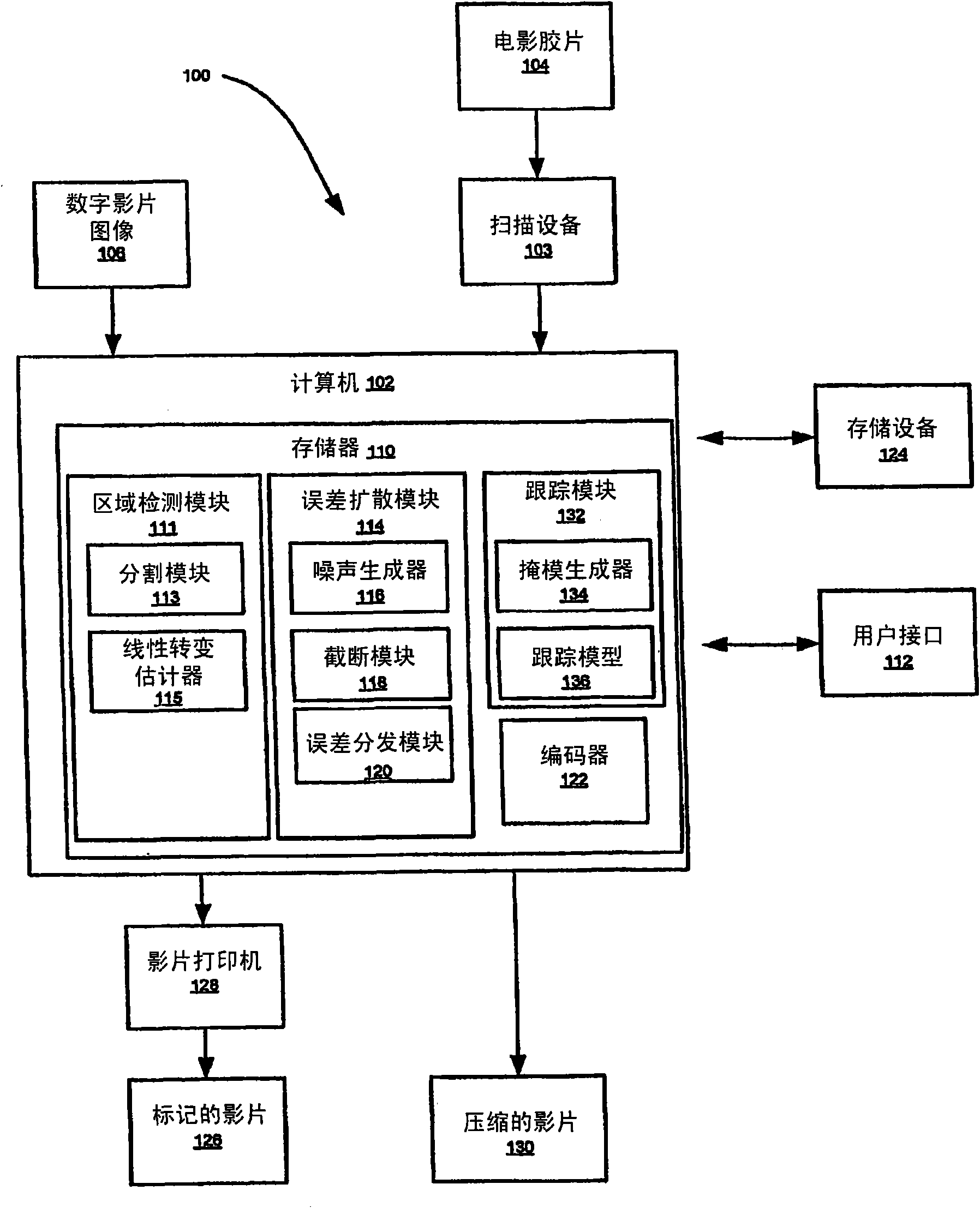
[0022] It should be understood that the elements shown in the figures may be implemented in various forms of hardware, software, or a combination thereof. Preferably, these elements are implemented by a combination of hardware and software on one or more suitably programmed general purpose devices, which may include a processor, memory and input / output interfaces.

[0023] This description illustrates the principles of the present disclosure. Accordingly, it should be appreciated that those skilled in the art can devise various arrangements for implementing the principles of this disclosure, which, although not explicitly described or shown herein, are included within the spirit and scope of this disclosure.

[0024] All examples and conditional language set forth herein are for teaching purposes to assist the reader in understanding the principles of the disclosure and the concepts contributed by the inventor to improve upon the prior art, and should not be construed as limit...


PUM


Abstract

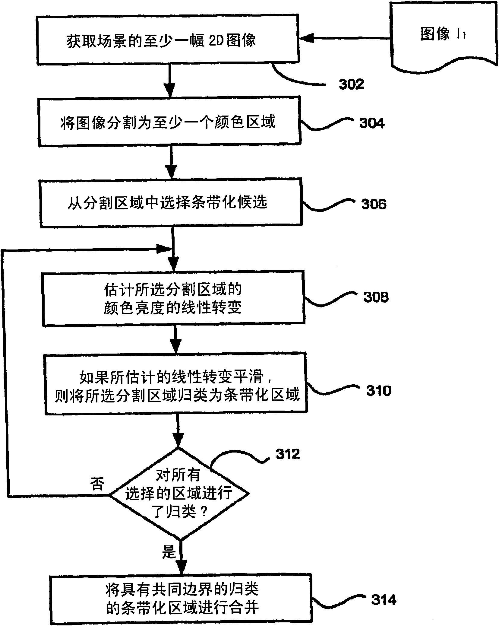
An apparatus and method of the present disclosure provides an automatic banding region detection function for detecting an image region that has a smooth linear transition of color intensity and is prone to have banding artifacts in image processing. The apparatus and method use a parametric model based approach to detect the banding region. The apparatus and method provide for segmenting at leastone first image into at least one homogeneous color region (304), estimating the linear transition of color intensity for the at least one homogeneous color region (308), and if the linear transitionof color intensity is substantially smooth, classifying the at least one homogenous color region as a banding region (310).

Description

technical field [0001] The present disclosure relates generally to digital image processing and display systems, and more particularly, to apparatus and methods for reducing artifacts in images, wherein areas in an image including artifacts are automatically detected without user intervention, For example, banding regions. Background technique [0002] Image artifacts are noticed during processing of digital images, or images such as image sequences in movies. A common artifact phenomenon is banding, in which bands of varying intensity and color level appear over the original smooth linear transition area of ​​the image. Processes like color correction, scaling, color space conversion, and compression can introduce banding effects. Banding is most prevalent in animated material, where the image is an artificial image with high frequency components and minimal noise. Any processing with limited bandwidth will inevitably cause aliasing, "ringing" or striping. [0003] The ...

Claims


Application Information

Patent Timeline
Patent Type & Authority Applications(China)
IPC IPC(8): G06T5/00H04N19/00H04N19/85H04N19/86
CPCG06T2207/10016G06T7/0081G06T7/408H04N9/646G06T2207/20141G06T5/001G06T2207/10024G06T7/11G06T7/90G06T7/187G06T7/00H04N5/21
Inventor 郭居张东庆
Owner THOMSON LICENSING SA
Learn More