Machine tool metering parallel

A pad iron and machine tool technology, applied in the directions of weighing, measuring force, supporting machines, etc., can solve problems such as precision reduction, machine tool vibration, machine tool deformation, etc., and achieve the effect of preventing machine tool offset

Inactive Publication Date: 2010-04-07
秦川机床工具集团股份公司
View PDF0 Cites 7 Cited by
  • Summary
  • Abstract
  • Description
  • Claims
  • Application Information

AI Technical Summary

Problems solved by technology

figure 1 The shims shown can only be adjusted in height. After the shims are placed under the bed, it is unknown whether the shims are solid or overloaded, whether they are stable or reliable. A machine tool has many shims. If the shims are uneven, Or some pad iron pads are solid, and some pad iron pads are not solid. After a period of time, it will cause deformation of the machine tool, cause machine tool vibration, and reduce precision. Stability is very important

Method used


Image

  • Machine tool metering parallel
  • Machine tool metering parallel
  • Machine tool metering parallel

Examples


Embodiment Construction

[0021] Attached below figure 2 , 3 , 4, 5, 6 describe an embodiment of the present invention.

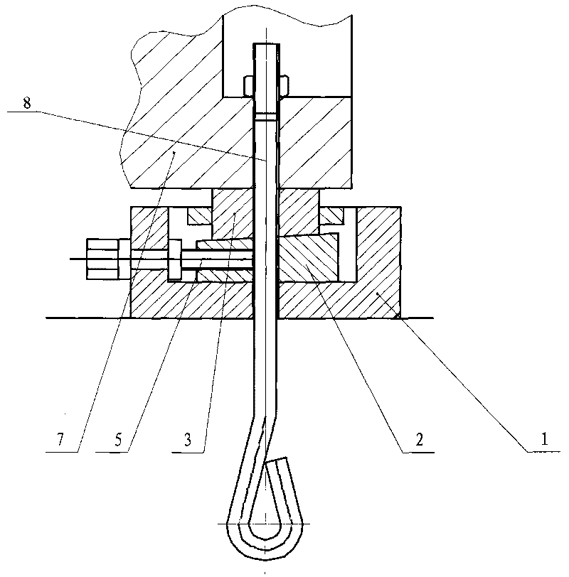
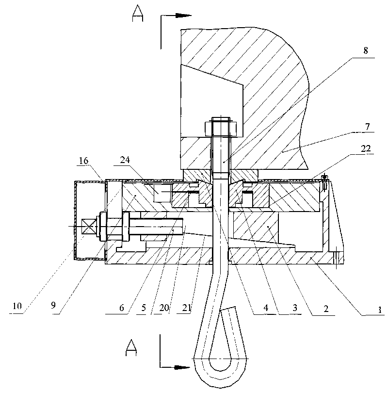
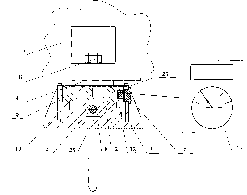
[0022] A machine tool metering pad iron, comprising a pad iron base 1, an inclined iron 2, a lower pad 3, an upper pad 4 and an adjusting bolt 5, the outer end of the adjusting bolt 5 is installed on the side wall of the pad iron base 1, and the inner end It is screwed on the screw hole on the side wall of the inclined iron 2. The bottom surface of pad iron seat 1 inner cavity is shaped on inclined plane 21, is shaped on groove 25 on inclined plane 21, and the upper end face of inclined iron 2 is the plane lower end face is inclined plane, and is shaped on boss I 18 on its inclined plane, inclined iron 2 Located on the inclined plane 21, and the boss I 18 is located in the groove 25; the pad seat 9 is placed on the upper end face of the inclined iron 2, the lower pad iron 3 is placed in the cavity 22 of the pad seat 9, and the upper pad 4 Located on the lower block 3, the upper ...


PUM


Abstract

A machine tool metering parallel comprises a parallel base, a wedge, a lower seat pad, an upper seat pad and an adjusting bolt, wherein the outer end of the adjusting bolt is arranged on the sidewall of the parallel base, the inner end is rotatablely arranged in the bolt of the sidewall of the wedge, an inclined plane is arranged on the bottom surface of the inner cavity of the parallel base, the inclined plane is provided with a groove, the upper end face of the wedge is a plane and the lower end face is an inclined surface provided with a boss I, the wedge is arranged on the inclined plane of the parallel base, the boss I is arranged in the groove; a seat pad base is arranged on the upper end face of the wedge, an upper parallel is arranged in the cavity of the seat pad base, the upper seat pad is above the lower seat pad, the arc convex of the low end face of the upper seat pad is matched with the arc concavity of the upper end face of the lower seat pad; in addition, through holes used for passing a foundation bolt through are arranged in the middles of the parallel base, the wedge, the seat pad base, the upper seat pad and the upper seat pad. The machine tool metering parallel of the invention can be used to measure and display the pressure of the parallel and provide reliable technical data for debugging and installing the machine tool.

Description

technical field [0001] The invention relates to a measuring pad iron of a machine tool with load measuring function. Background technique [0002] Machine tool shim iron is an auxiliary part used for machine tool installation and machine level adjustment. The shim iron is placed under the machine base and fixed with anchor bolts. Existing machine tool horns such as figure 1 As shown, it is composed of iron seat, lower block, upper block, adjusting bolt and other parts. The lower block is placed on the iron seat, and the adjusting bolt is connected with the lower block. Matching the inclined surface of the upper end surface of the block, the height of the upper block can be adjusted by adjusting the position of the lower block through the bolts. The machine tool is placed on the upper block, and different numbers of parallel irons are evenly placed under the machine base according to the weight and dimensions of the machine tool during use. figure 1 The shims shown can onl...

Claims


Application Information

Patent Timeline
Patent Type & Authority Applications(China)
IPC IPC(8): B23Q1/72F16M7/00G01L1/00G01M1/12G01G19/62
Inventor 杨奇俊胡万良吴良材
Owner 秦川机床工具集团股份公司
Why Eureka
Try Eureka