Column joint structure of building and connection method thereof

A technology of column joints and buildings, which is applied in the direction of building structure and construction, can solve the problems of long waiting period, difficult operation, difficult construction, etc., and achieve fast installation, convenient precision control, and easy installation Effect

Inactive Publication Date: 2010-04-07
黄亚茹 +1
View PDF0 Cites 10 Cited by
  • Summary
  • Abstract
  • Description
  • Claims
  • Application Information

AI Technical Summary

Problems solved by technology

During the period, the correct position of the components is maintained by temporary support, and the load cannot be applied until the strength of the cast-in-place concrete is satisfied. There are problems such as complex reinforcement layout, difficult operation, difficult quality assurance, and long waiting period for the operation, especially the problem of waiting for the strength of

Method used


Image

  • Column joint structure of building and connection method thereof
  • Column joint structure of building and connection method thereof

Examples


Embodiment Construction

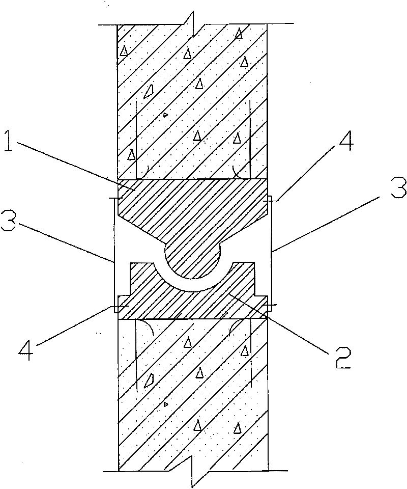
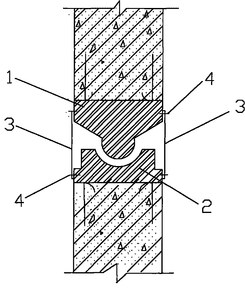
[0028] see figure 1 , in this embodiment, between the upper column and the lower column, the interconnected column joints adopt a concave-convex structural form, and the concave-convex structural form is to set a concave spherical surface at the center of the column top surface of the lower column, and the relative position The column bottom surface of the upper column is set as a convex spherical surface, and the concave spherical surface and the convex spherical surface form a joint that can rotate relative to each other. The outer peripheries of the upper column and the lower column are evenly distributed. connecting plate.

[0029] In specific implementation, the corresponding structural settings also include:

[0030] Both the concave spherical surface and the convex spherical surface are made of cast steel or high-strength materials. They are respectively fixed on the top of the lower column and the bottom of the upper column in a pre-embedded manner. It is required to ...


PUM


Abstract

The invention discloses a column joint structure of a building and a connection method thereof. Mutually connected column joints between an upper layer column and a lower layer column are of concave-convex matching structural forms, that is, a concave spherical surface is arranged in the center of the column top surface of the lower layer column, while a convex spherical surface is arranged on the column bottom surface of the upper layer column at an opposite position; the concave spherical surface and the convex spherical surface form joints capable of rotating relatively; and connecting plates connected between the upper layer column and the lower layer column along a longitudinal direction are uniformly distributed on the peripheries of the upper layer column and the lower layer column. The column joint structure of the building can enable a pre-fabricated structure to fully meet the requirements of heavy load, crake resistance, strong integrity and rapid industrial production.

Description

technical field [0001] The invention relates to a structure of column joints of buildings and a connection method thereof. Background technique [0002] At present, the column joint structure of buildings can be divided into prefabricated structure construction methods, and the connection of load-bearing components can be divided into wet connection and dry connection. Wet connections require the pouring of concrete or grout between the two members being joined. To ensure the integrity of the connection, the two members need to be lapped or mechanically connected with protruding reinforcement before pouring the concrete. This wet connection method is to form cast-in-place reinforced concrete nodes by pouring concrete after the steel bars are connected. [0003] Dry connection is to implant steel plates or other steel parts in the two components to be connected, and mechanically connect the outstretched steel plates of the two components by bolts or welding to achieve the p...

Claims


Application Information

Patent Timeline
IPC IPC(8): E04B1/18E04B1/21
Inventor 袁斌黄亚茹
Owner 黄亚茹
Why Eureka
Try Eureka