
Self-condensing gas-water separating device of water-ring vacuum pump set

A technology of gas-water separation device and water-ring vacuum pump, which is applied to pump components, mechanical equipment, variable-capacity pump components, etc., can solve the problems affecting the working performance of vacuum pumps, poor pumping efficiency of vacuum pumps, and no cooling effect. Long-term stable operation, improve cooling effect, save tap water effect

Inactive Publication Date: 2010-04-07
山东精工泵业有限公司
View PDF0 Cites 5 Cited by
  • Summary
  • Abstract
  • Description
  • Claims
  • Application Information

AI Technical Summary

Problems solved by technology

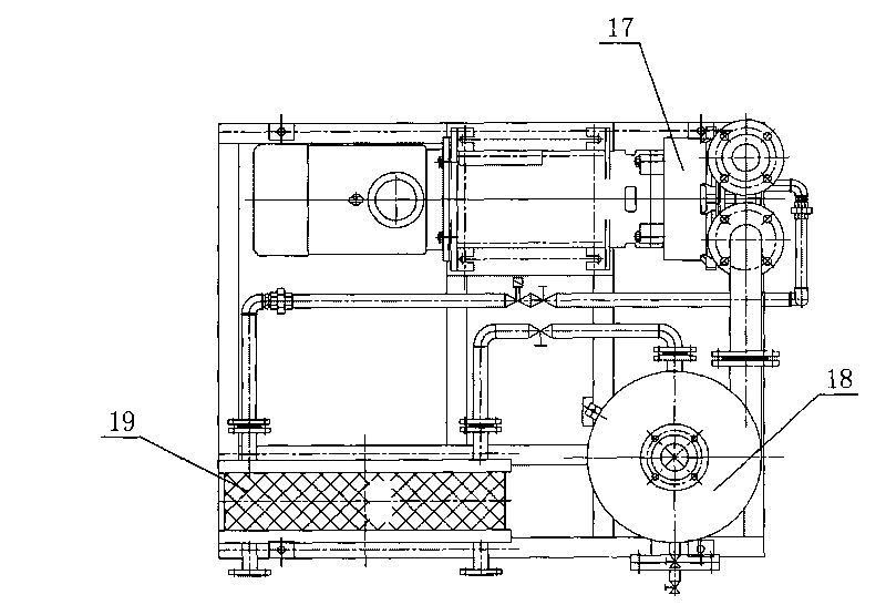
[0002] For the needs of the working process, the existing water ring vacuum pump unit is equipped with a plate heat exchanger and a gas-water separator respectively. The plate heat exchanger consumes a large amount of water in the process of cooling the working fluid of the vacuum pump, and the cooling effect is poor. , it is difficult to meet the requirement that the working fluid should maintain a stable low temperature when the water ring vacuum pump is running. Theoretically, it requires 15°C. Naturally, the lower the better, but it is difficult to achieve in practice. During long-term operation, the temperature of the working fluid rises to 50 ℃, the pumping efficiency of the vacuum pump is very poor. If the temperature is higher, the vacuum pump will basically lose the function of pumping the process system, which directly affects the working performance of the vacuum pump, and the gas-water separator can only separate gas and water. , no cooling effect

Method used


Image

  • Self-condensing gas-water separating device of water-ring vacuum pump set
  • Self-condensing gas-water separating device of water-ring vacuum pump set
  • Self-condensing gas-water separating device of water-ring vacuum pump set

Examples


Embodiment Construction

[0021] The present invention will be further described in conjunction with the accompanying drawings of the above-mentioned embodiments.

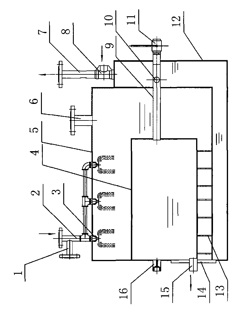
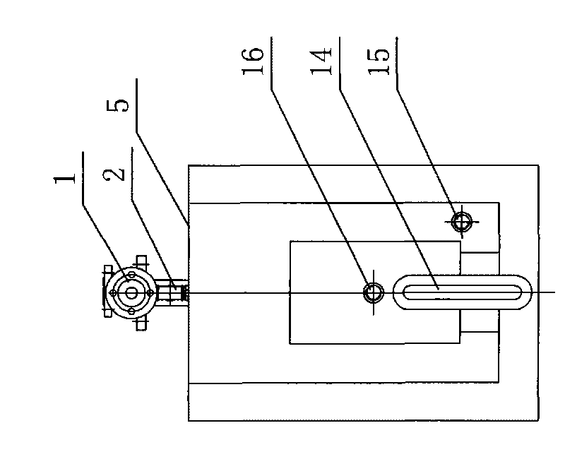
[0022] Such as figure 1 , figure 2 As shown, the self-condensing gas-water separation device of the water ring vacuum pump unit according to the present invention is provided with an intermediate water tank 5, the interior of the intermediate water tank 5 is provided with an inner condensation tank 4, the middle water tank 5 is outsourced with an outer condensation tank 12, and the middle water tank 5 The top is provided with an exhaust port 6 and the pump working fluid return port 2, the bottom is provided with a pump working fluid supply port 15, and the top of the middle water tank 5 is provided with a spray head 3, several of which can be arranged side by side. The spray head 3 is connected to the pump working On the liquid return port 2, the working fluid return port 2 is connected to the working liquid replenishment port 1, and a co...


PUM


Abstract

The invention relates to a self-condensing gas-water separating device of a water-ring vacuum pump set, belonging to the auxiliary devices of the water-ring vacuum pump set. The device is provided with a middle water tank in which an inner condensing tank is arranged and out of which an outer condensing tank is arranged. An exhaust port and a pump working solution return port are arranged at the top of the middle water tank, and a pump working solution supply port is arranged at the bottom of the middle water tank. The inner condensing tank and the outer condensing tank are respectively communicated with a water replenishing tube and an exhaust tube. The device is designed based on the principle that water is rapidly evaporated and cooled under negative pressure and skillfully realizes the functions of gas-water separating and water-ring vacuum pump working solution cooling, removes the plate type heat exchanger and gas-water separator used by background technology, simplifies the structure, has the characteristics of light weight and low manufacturing and using costs, can save the raw materials by 80% and reduce the cost by 60%, not only improve the effect on cooling the water-ring vacuum pump working solution and ensure long-term stable running of the water-ring vacuum pump, but also save lots of running water.

Description

technical field [0001] The invention relates to a self-condensing gas-water separation device of a water ring vacuum pump unit, which belongs to the auxiliary device of the water ring vacuum pump unit. Background technique [0002] For the needs of the working process, the existing water ring vacuum pump unit is equipped with a plate heat exchanger and a gas-water separator respectively. The plate heat exchanger consumes a large amount of water in the process of cooling the working fluid of the vacuum pump, and the cooling effect is poor. , it is difficult to meet the requirement that the working fluid should maintain a stable low temperature when the water ring vacuum pump is running. Theoretically, it requires 15°C. Naturally, the lower the better, but it is difficult to achieve in practice. During long-term operation, the temperature of the working fluid rises to 50 ℃, the pumping efficiency of the vacuum pump is very poor. If the temperature is higher, the vacuum pump wi...

Claims


Application Information

Patent Timeline
Patent Type & Authority Applications(China)
IPC IPC(8): F04B39/16
Inventor 李峰
Owner 山东精工泵业有限公司
Learn More