Internal linkage type reducing valve

A pressure reducing valve and low-pressure chamber technology, applied in the field of interlocking pressure reducing valves, can solve the problems affecting the pressure reducing performance of the pressure reducing valve, the structure of the pressure reducing valve is complicated, and the performance is not stable enough, so as to save material costs and have a simple structure , The effect of convenient processing

Active Publication Date: 2010-04-07
张家和
View PDF0 Cites 3 Cited by
  • Summary
  • Abstract
  • Description
  • Claims
  • Application Information

AI Technical Summary

Problems solved by technology

However, in the sealed connection between the decompression assembly and the main body, the sealing performance caused by its structure is not good; in the long-term work of the rubber sheet, the middle part needs to be constantly moved or deformed, which will cause the sealing performance between the edge part and the main body Poor, which in turn affects the decompression performance of the pressure reducing valve, making its performance not stable enough
Moreover, this kind of pressure reducing valve has complex structure, many parts and high cost.

Method used


Image

  • Internal linkage type reducing valve
  • Internal linkage type reducing valve
  • Internal linkage type reducing valve

Examples


Embodiment

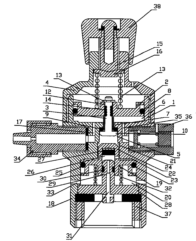
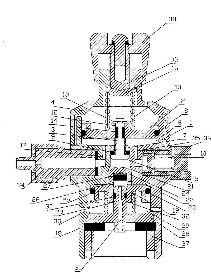
[0030] Example: such as figure 1 , figure 2 As shown, the internal linkage pressure reducing valve includes a main body 1, a piston 2, an intake switch shaft 3, a valve cover 4, a high pressure chamber 5, a low pressure chamber 6, and a pre-stage pressure reducing mechanism. The cross-sectional area of ​​the low pressure chamber 6 is larger than that of the high pressure chamber. The chamber 5 has a large cross-sectional area, and the low-pressure chamber 6 and the high-pressure chamber 5 are connected through the channel 7; Located in the high-pressure chamber 5, the other end passes through the channel 7 and enters the low-pressure chamber 6 to connect with the piston 2; the end of the intake switch shaft 3 located in the high-pressure chamber 5 is provided with an intake seal ring 9, and the intake switch shaft 3 is sealed by the intake air. The end face of the ring 9 and the channel 7 located in the low-pressure chamber 6 are dynamically sealed.

[0031] Such as figur...


PUM


Abstract

The invention discloses an internal linkage type reducing valve, which is characterized by comprising a main body, a piston, an air inlet switch shaft, a valve cover, a high-pressure chamber, a low-pressure chamber and a preceding stage pressure-reducing mechanism, wherein the sectional area of the low-pressure chamber is larger than that of the high-pressure chamber, and the low-pressure chamber is communicated with the high-pressure chamber through a passage; the piston is positioned in the low-pressure chamber, the edge of the piston is in sealed contact with the side wall of the low-pressure chamber through an outer sealing ring of the piston; one end of the air inlet switch shaft is positioned in the high-pressure chamber, while the other end enters the low-pressure chamber by passing through the passage and is connected with the piston; one end of the air inlet switch shaft positioned in the high-pressure chamber is provided with an air inlet sealing ring; and the end face of the end of the air inlet switch shaft positioned in the low-pressure chamber is sealed movably through the air inlet sealing ring and the passage. The internal linkage type reducing valve is strong and stable in pressure-reducing performance, has a simple structure, and saves material costs; all large components are made of metal and can play a role in flame retarding and explosion protection; besides, the internal linkage type reducing valve can be used in various household electrical appliances or apparatuses such as a beer machine, a red wine machine, an aerated water machine and the like.

Description

technical field [0001] The invention relates to an internally linked pressure reducing valve, in particular to an internally linked pressure reducing valve which converts high-pressure gas into low-pressure gas. Background technique [0002] In the prior art, the needle-type adjustable pressure reducing valve is mainly composed of a main body, a pressure regulating screw, a rubber sheet, a pressure reducing assembly and other components. However, in the sealed connection between the decompression assembly and the main body, the sealing performance caused by its structure is not good; in the long-term work of the rubber sheet, the middle part needs to be constantly moved or deformed, which will cause the sealing performance between the edge part and the main body Poor, which in turn affects the decompression performance of the pressure reducing valve, making its performance not stable enough. Moreover, this pressure reducing valve has complex structure, many parts and high c...

Claims


Application Information

Patent Timeline
Patent Type & Authority Applications(China)
IPC IPC(8): F16K17/04F16K31/50F16K47/00G05D16/10
Inventor 张家和
Owner 张家和
Why Eureka
Try Eureka