
Deformable omni-directional moving mechanism

An all-round mobile and all-round technology, applied in the field of robotics, can solve the problems of inability to change shape, adjustable range limit, etc., and achieve the effect of simple structure and easy realization

Inactive Publication Date: 2010-04-14
浙江瑞鹏机器人科技有限公司
View PDF1 Cites 4 Cited by
  • Summary
  • Abstract
  • Description
  • Claims
  • Application Information

AI Technical Summary

Problems solved by technology

This mechanism only realizes the adjustment of part of the position and attitude of the wheel, and the mechanism itself cannot change its shape, and is limited by the mechanism support frame, and the adjustable range is limited

Method used


Image

  • Deformable omni-directional moving mechanism
  • Deformable omni-directional moving mechanism
  • Deformable omni-directional moving mechanism

Examples


Embodiment Construction

[0019] The embodiments of the present invention will be described in detail below. This embodiment is implemented on the premise of the technical solution of the present invention. Detailed implementation modes and specific operation procedures are given, but the protection scope of the present invention is not limited to the following implementations. example.

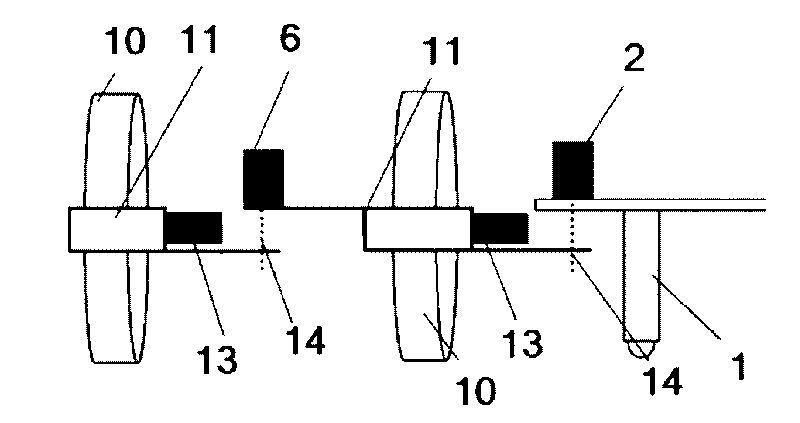
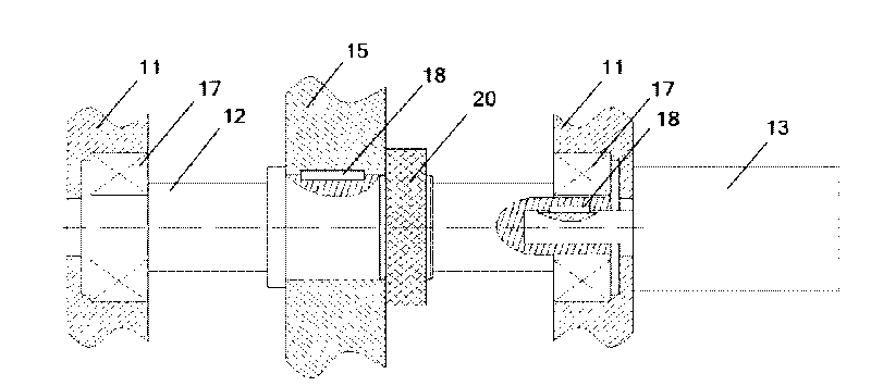
[0020] Such as figure 1 As shown, the present invention includes: four motion units, a work platform 1 and four joint swing motors, wherein: the first joint swing motor 2 and the second joint swing motor 3 are fixedly arranged on the left and right sides of the work platform 1, respectively, The output shafts of the first joint swing motor 2 and the second joint swing motor 3 are connected to the first movement unit 4 and the second movement unit 5, respectively. The first movement unit 4 and the second movement unit 5 are respectively provided with a third joint The output shafts of the swing motor 6 and the fourth join...


PUM


Abstract

A deformable omni-directional moving mechanism belongs to the technical field of robot, and comprises four motion units, an operation platform and a plurality of joint swaying motors, wherein the first joint swaying motor and the second joint swaying motor are respectively fixed at the left side and the right side of the operation platform, the output shafts of the first and the second joint swaying motors are respectively connected with the first motion unit and the second motion unit, the third joint swaying motor and the fourth joint swaying motor are respectively arranged on the first motion unit and the second motion unit, and the output shafts of the third and the fourth joint swaying motors are respectively connected with the third motion unit and the fourth motion unit. The deformable omni-directional moving mechanism can not only change positions and postures of each omni wheel within a long range but also realize self-deformation, is adaptive to various complex environments, and has a good characteristic of trafficability.

Description

Technical field [0001] The invention relates to a device in the technical field of robots, in particular to a deformable omnidirectional moving mechanism. Background technique [0002] In recent years, earthquakes, mine disasters and other disasters have occurred frequently. In various emergency and dangerous situations, the injured and trapped people need to be treated in time. However, due to the complex environment, it is difficult for rescuers to penetrate deep into the disaster area in time, resulting in precious "golden "Rescue time passed in vain, and many trapped people lost their lives. Disaster relief robots came into being. They can reach areas where people cannot enter, detect situations for rescuers, provide guidance for rescue work, and moreover, can directly rescue trapped people from the rubble. Disaster relief robots are an important branch of robots. Many research institutions at home and abroad have done a lot of research and developed robots of various struct...

Claims


Application Information

Patent Timeline
IPC IPC(8): B25J5/00
Inventor 赵一阳
Owner 浙江瑞鹏机器人科技有限公司
Learn More