Damping device

The technology of a shock absorbing device and a flange is applied in the field of buffer shock absorbing devices, which can solve the problems of poor shock absorbing effect, influence life, short service life, etc., and achieve the effect of improving shock absorbing efficiency and prolonging service life.

Inactive Publication Date: 2010-04-14
DONGGUAN ANWELL DIGITAL MASCH CO LTD
View PDF0 Cites 9 Cited by
  • Summary
  • Abstract
  • Description
  • Claims
  • Application Information

AI Technical Summary

Problems solved by technology

Compared with the present invention, the shock absorption of the first kind is relatively passive; the second kind has poor portability and short service life compared with the present invention
The method of increasing inertia to reduce vibration has two disadvantages: 1. The shock absorption is relatively passive, because this method simplifies the suction pipeline, and the rigid connection between the pump body and the cavity is adopted, and the vibration can still be directly transmitted to the cavity. , the vibration cannot be reduced from the source; 2. The cost is high, because increasing the quality requires increasing the material, and also increasing the difficulty of processing
There are three disadvantages in the structure of using bellows connection to reduce vibration: 1. Short life, because the bellows are not protected by any device, they will be subject to some flexible force, and the compression ratio of the bellows before and after air extraction will be too large, thus Affect the life; 2. Poor portability, because the pump body is placed in isolation; 3; Affect the pumping speed of the gas in the cavity, because the bellows of this shock absorption method are generally long and the flow resistance of the gas is too large
[0004] Therefore, in order to overcome the characteristics of poor damping effect and short service life of conventional shock absorbing devices, there is an urgent need for a shock absorbing device with compact structure, good shock absorbing effect, low cost and long service life.

Method used


Image

  • Damping device
  • Damping device
  • Damping device

Examples


Embodiment Construction

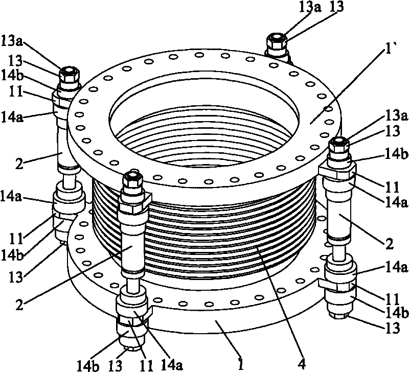
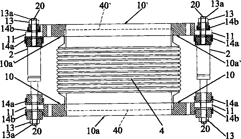
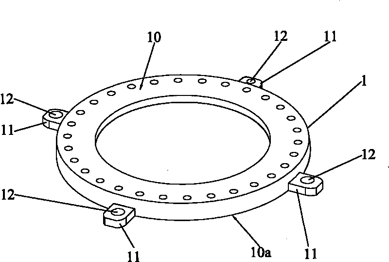
[0015] Embodiments of the present invention will now be described with reference to the drawings, in which like reference numerals represent like elements. As mentioned above, such as figure 1 and figure 2 As shown, the buffer and shock absorbing device 100 provided by the present invention is installed between the vacuum pump and the vacuum chamber. The buffer and shock absorbing device 100 includes a first flange 1, a second flange 1' and a bellows 4. The The first flange 1 has an upper surface 10 and a lower surface 10a, the second flange 1' has an upper surface 10' and a lower surface 10a', the upper surface 10' of the second flange 1' is connected to the vacuum The cavity is sealed and connected, the lower surface 10a of the first flange 1 is sealed and connected with the vacuum pump, the bellows 4 has a first open end 40 and a second open end 40', the first open end of the bellows 4 The open end 40 is in sealing connection with the upper surface 10 of the first flange...


PUM


Abstract

The invention discloses a damping device which comprises a first flange, a second flange and a corrugated tube. The upper surface of the second flange is hermetically connected with a vacuum cavity; the lower surface of the first flange is hermetically connected with a vacuum pump; and the corrugated tube is provided with a first opening end and a second opening end. The first opening end of the corrugated tube is hermetically connected with the upper surface of the first flange; and the second opening end of the corrugated tube is hermetically connected with the lower surface of the second flange. The first flange and the second flange both have circular ring structures which are provided with uniformly bulges protruding outwards and the bulges are provided with mounting holes. The damping device also comprises a gas spring and a nut, wherein two ends of the gas spring are respectively provided with a connecting part which correspondingly penetrates through the mounting holes of the first flange and the second flange and are meshed with the nut; the connecting part is provided with an external thread; and the nut is provided with an internal thread meshed with the external thread. The damping device has the advantages of compact structure, good damping effect, low cost and long service life.

Description

technical field [0001] The present invention relates to a shock absorbing device mechanical equipment, in particular to a shock absorbing device for shock absorbing a vacuum cavity Background technique [0002] In the automated and semi-automated production of the modern semiconductor industry, lithographic printing equipment, optical fields, and electronic equipment industries and other industrial production and experimental processes, high-stability anti-shock technology is required, and the harm caused by vibration is undoubtedly fatal. However, on the one hand, the floor under our feet is subject to various disturbances from the outside world all the time, such as earthquakes, nearby vehicles, heavy machinery in motion, walking staff and all other troubles It will bring large or small vibrations to the floor. It has no effect on substances with low anti-vibration requirements, but it is indeed destructive to substances with high anti-vibration requirements, such as in th...

Claims


Application Information

Patent Timeline
IPC IPC(8): F04B39/00
Inventor 杨明生刘惠森范继良叶宗锋王曼媛王勇
Owner DONGGUAN ANWELL DIGITAL MASCH CO LTD
Why Eureka
Try Eureka