Surging current suppression method

A technology for inrush current and circuit suppression, applied in electrical components, circuit devices, emergency protection circuit devices for limiting overcurrent/overvoltage, etc. problem, to achieve the effect of suppressing large current impact, avoiding electromagnetic interference, and low installation cost

Inactive Publication Date: 2010-04-14
LANGCHAO ELECTRONIC INFORMATION IND CO LTD
View PDF0 Cites 10 Cited by
  • Summary
  • Abstract
  • Description
  • Claims
  • Application Information

AI Technical Summary

Problems solved by technology

The cumulative effect of multiple small surges can also cause semiconductor device performance degradation, equipment failure and shortened life, resulting in reduced productivity
Moreover, the surge current will destroy the power supply quality of the grid, not only generate serious electromagnetic interference, but also affect other equipment connected to the grid

Method used


Image

  • Surging current suppression method
  • Surging current suppression method
  • Surging current suppression method

Examples


Embodiment 1

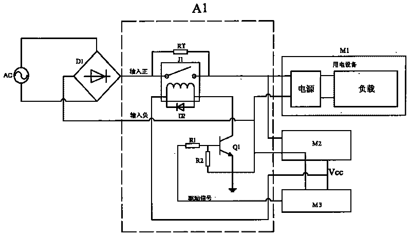
[0015] A surge current suppression circuit is connected in series between the power supply port of the electrical equipment and the mains, and the impedance of the power supply terminal of the electrical equipment is adjusted through the surge current suppression circuit, effectively suppressing the large current impact generated by the normal startup of the electrical equipment.

[0016] The circuit connection is as follows: the inrush current suppression circuit A1 includes a thermistor-RT, a relay-J1 and a transistor-Q1. After the thermistor-RT and relay-J1 are connected in parallel, one end is connected to the rectifier bridge D1, and the other end is respectively connected to the electrical equipment M1 is connected to the low-power auxiliary power supply M2, the low-power auxiliary power supply M2 is connected to the relay drive circuit M3, the relay drive circuit M3 is connected to the relay-J1, and the circuit connected between the relay drive circuit M3 and the relay-J1...

Embodiment 2

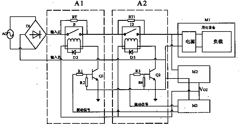
[0021] Two inrush current suppression circuits are connected in series between the power supply port of the electrical equipment and the mains, and the impedance of the power supply terminal of the electrical equipment is adjusted through the surge current suppression circuit, effectively suppressing the large current impact generated by the normal startup of the electrical equipment.

[0022] The circuit connection is as follows: the surge current suppression circuit A1 and the surge current suppression circuit A2 are connected in series between the rectifier bridge D1 and the electrical equipment M1; the surge current suppression circuit A1 includes a thermistor-RT, a relay-J1 and a transistor-Q1 , the thermistor-RT and relay-J1 are connected in parallel, and one end is connected to the rectifier bridge D1, and the other end is connected to the surge current suppression circuit A2; the collector of the triode-Q1 used to improve the current driving capability is connected to th...


PUM


Abstract

The invention discloses a surging current suppression method, which belongs to the application technology of device power ports. The method is formed as follows: at least one surging current suppression circuit is in series connection between an electric equipment power port and a commercial power, and large current impacts produced when electric equipment is started routinely can be effectively suppressed by adjusting impedance of an electric equipment power terminal through the surging current suppression circuit. The surging current suppression method can simultaneously guarantee power supply quality of a power network, avoid producing severe electromagnetic interference and not affect other properties of equipment while effectively suppress surging current.

Description

technical field [0001] The invention relates to the application technology of the power supply interface of equipment, in particular to a surge current suppression method. Background technique [0002] Inrush current is the peak current that flows into the power supply device at the moment the power is turned on. The surge occurs for a very short time, probably at the microsecond level, and the magnitude of the current is more than twice the normal value. This peak current is much greater than the steady-state input current due to the rapid charging of the input filter capacitor. If the surge current exceeds the capacity of the device, the device will be completely destroyed or its life will be greatly reduced. The cumulative effect of multiple small surges can also cause semiconductor device performance degradation, equipment failure and shortened lifetime, resulting in reduced productivity. Moreover, the surge current will destroy the power supply quality of the grid, n...

Claims


Application Information

Patent Timeline
IPC IPC(8): H02H9/04
Inventor 吴安
Owner LANGCHAO ELECTRONIC INFORMATION IND CO LTD
Why Eureka
Try Eureka