Surge current suppression circuit and method

A surge current and suppression circuit technology, applied in battery circuit devices, emergency protection circuit devices for limiting overcurrent/overvoltage, circuit devices, etc. , the effect of inrush current suppression

Active Publication Date: 2020-06-26
重庆宏一电气有限公司
View PDF6 Cites 6 Cited by
  • Summary
  • Abstract
  • Description
  • Claims
  • Application Information

AI Technical Summary

Problems solved by technology

However, it increases the volume of the converter, which is contrary to the de

Method used


Image

  • Surge current suppression circuit and method
  • Surge current suppression circuit and method
  • Surge current suppression circuit and method

Examples


Example Embodiment

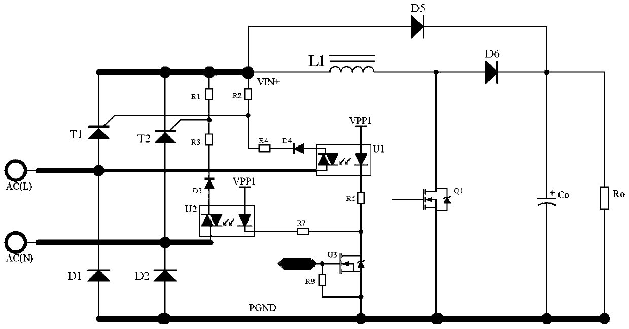
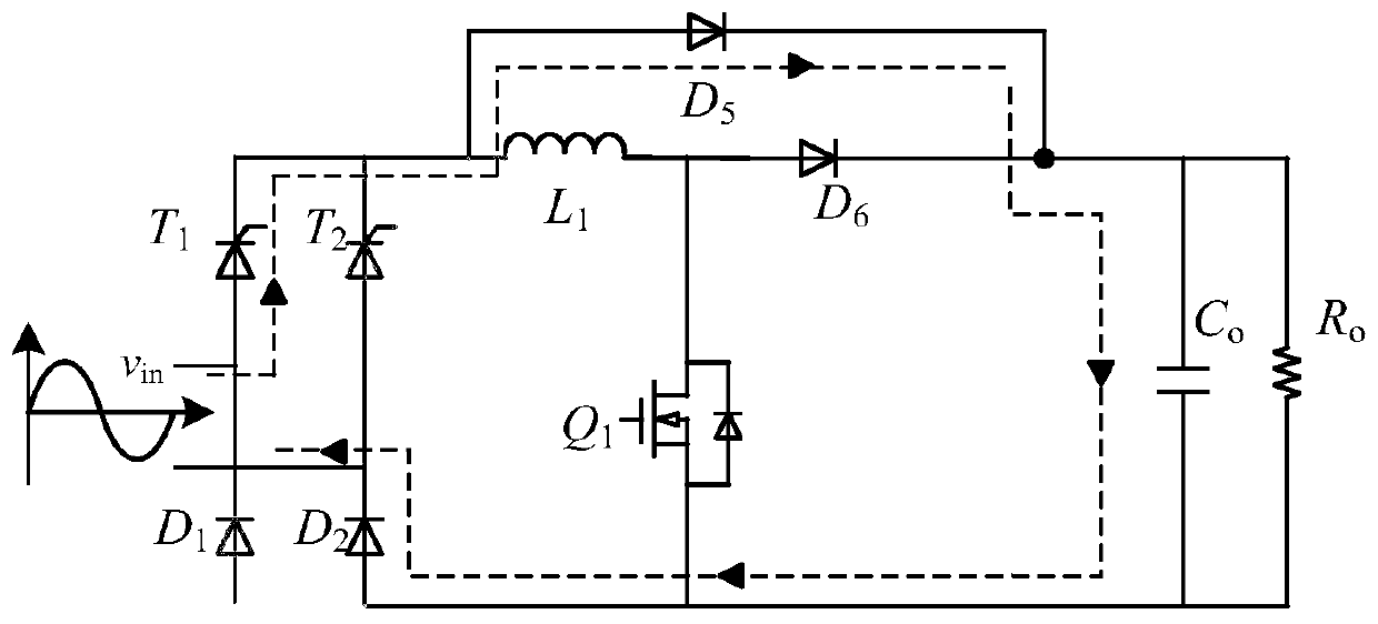
[0024] A surge current suppression circuit, comprising a charging circuit and a digital control chip, the charging circuit is used to obtain alternating current and charge an output capacitor; the charging circuit includes a thyristor and a driving circuit, the anode end of the thyristor is used for taking electricity from the alternating current line, and the thyristor The cathode terminal of the thyristor is used to send power to the output capacitor, and the gate terminal of the thyristor obtains the turn-on driving voltage from the AC line through the driving circuit.

[0025] The drive circuit includes a voltage divider circuit and a switch circuit connected in series; the switch circuit is used to turn on or off the drive circuit according to the control signal of the digital control chip, the cathode end of the thyristor is connected to the low voltage point of the voltage divider circuit, and the gate of the thyristor is connected. The terminal is connected to the high ...


PUM


Abstract

The invention discloses a surge current suppression circuit and method, and the suppression method employs the surge current suppression circuit for suppression. The surge current suppression circuitcomprises a charging circuit and a digital control chip, and the charging circuit is used for obtaining an alternating current and charging an output capacitor; the charging circuit comprises a thyristor and a driving circuit, and the gate end of the thyristor obtains conduction driving voltage from the alternating current line through the driving circuit; a pulse type charging control program isconfigured in the digital control chip, and the pulse type charging control program is used for controlling the charging circuit to perform pulse type charging on the output capacitor according to theconduction interval modulation program and the conduction time point determination program; and the conduction interval modulation program is used for modulating the conduction interval of the thyristor to be conducted only in the absolute value reduction interval of the input alternating-current voltage. The influence of the environment temperature on the surge current suppression effect is overcome, and the structure is simple and ingenious.

Description

technical field [0001] The present invention relates to the technical field of surge current suppression, in particular to a surge current suppression circuit, and also to a surge current suppression method based on the surge current suppression circuit. Background technique [0002] Inrush current is a common problem in the start-up process of power electronic devices, especially in high-power applications. Many circuits need to pre-charge the output capacitor of the subsequent stage to ensure the reliable operation of power devices. Therefore, during the start-up transient Generate a large inrush current. [0003] At present, the most commonly used inrush current limiting method at home and abroad is to connect negative temperature coefficient thermistor current limiting resistors in series, but there are still some problems. For example, the current limiting effect of NTC resistors is greatly affected by the ambient temperature. When starting at low temperature (below ze...

Claims


Application Information

Patent Timeline
IPC IPC(8): H02H9/02H02J7/02H02J7/04H02J7/00
CPCH02H9/02
Inventor 章治国廖鸣宇易嘉欣杜吉祥李山
Owner 重庆宏一电气有限公司
Why Eureka
Try Eureka