Quick power-down module of low-voltage equipment

A technology of low-voltage equipment and electrical modules, applied in the field of rapid power-down modules, which can solve problems such as complex circuit forms and lack of surge current protection measures for PNP transistors

Active Publication Date: 2015-01-21
厦门福信光电集成有限公司
View PDF10 Cites 6 Cited by
  • Summary
  • Abstract
  • Description
  • Claims
  • Application Information

AI Technical Summary

Problems solved by technology

For example, the fast PNP transistor turn-off circuit of patent CN 103152023 A realizes fast turn-off of the PNP transistor when the power is turned off by providing reverse drive current for the base of the PNP transistor. Protection measures for surge current generated by power-on

Method used


Image

  • Quick power-down module of low-voltage equipment
  • Quick power-down module of low-voltage equipment

Examples


Embodiment 1

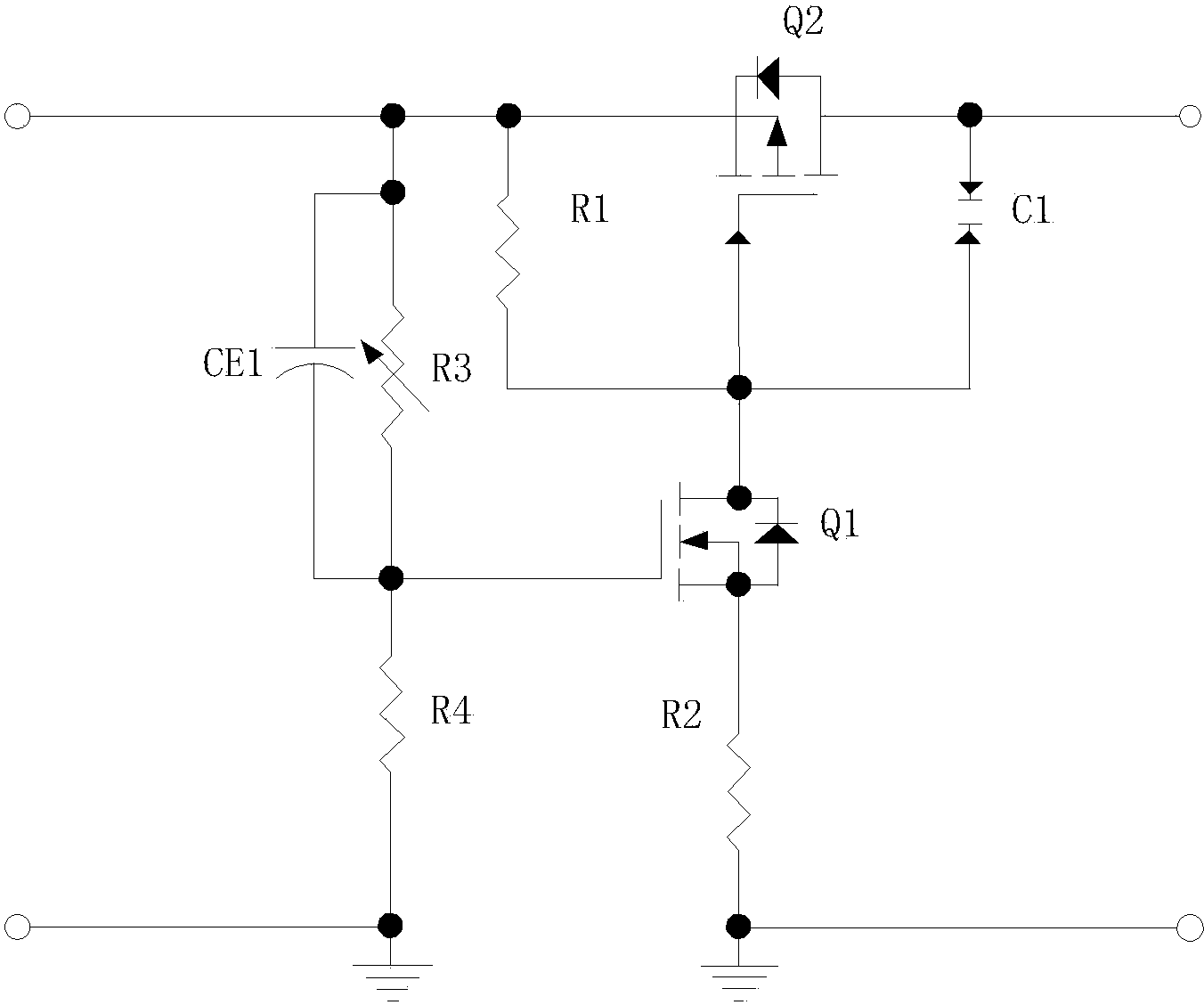
[0018] The circuit diagram of the first preferred embodiment of the fast power-down module of a low-voltage equipment of the present invention is as follows figure 2 As shown, it includes: switch field effect transistor, driving field effect transistor, capacitor CE1, resistor R1, adjustable resistor R3, resistor R4, resistor R2, and capacitor C1.

[0019] The switch field effect transistor Q2 is the power switch of the fast power-down module of the low-voltage equipment, its switch input pole is used as the input end of the circuit, its switch output pole is used as the output end of the circuit, and its switch control pole is connected with the described drive The driving input pole of the field effect transistor Q1 is connected;

[0020] The capacitor CE1 is connected in parallel with the adjustable resistor R3, the first node of which is connected in parallel with the switch input pole of the switch field effect transistor Q2, and the second node is connected to the groun...

Embodiment 2

[0028] As an alternative to Embodiment 1, it can also be an equivalent circuit diagram of an N-channel enhanced field effect transistor as a switch field effect transistor and a P-channel enhanced field effect transistor as a driving field effect transistor; or an N-channel enhanced field effect transistor. The equivalent circuit diagram of the FET as the switch FET and the N-channel enhanced FET as the driving FET; or the P-channel enhanced FET as the switch FET, and the P-channel enhanced FET as the driving FET. The tube is used as the equivalent circuit diagram of the drive field effect tube.


PUM


Abstract

The invention relates to a quick power-down device, in particular to a quick power-down module of low-voltage equipment. The quick power-down module comprises a switch field-effect tube, a drive field-effect tube, a capacitor CE1, a resistor R1, a resistor R3 and a resistor R4. According to the quick power-down module of the low-voltage equipment, quick breakover and quick disconnection can be achieved when the drive field-effect tube is powered on or powered off through the capacitor CE1, the adjustable resistor R3 and the resistor R4, due to the fact that the resistor R3 is adjustable, different drive field-effect tubes can be precisely adjusted to the threshold voltage of the drive field-effect tubes, meanwhile, the switch field-effect tube is started slowly when the circuit input end is powered on through the capacitor C1, the resistor R1 and the resistor R2, and the switch field-effect tube is protected from being broken down by the inrush current in the power-on process.

Description

technical field [0001] The invention relates to a fast power-down module, in particular to a fast power-down module for low-voltage equipment. Background technique [0002] In some devices, it is often required that the data in the internal and external RAM of the processor CPU will not be lost when the power is turned off, and when the power is turned on again, the data in the RAM can be preserved intact, which requires sufficient protection for the CPU system when the power is turned off. Time processing and data storage, etc., or in some communication equipment, in order to improve the work efficiency of monitoring personnel, it is required that the user terminal can provide an alarm to the central office when it is powered on / off. Some devices are powered off quickly, while some circuits are powered off slowly. The fast power-off module is born to speed up power-off, such as figure 1 As described in the block diagram of a preferred application embodiment, the fast powe...

Claims


Application Information

Patent Timeline
Patent Type & Authority Applications(China)
IPC IPC(8): H03K17/08
Inventor 梁志达洪亚德李亚楼
Owner 厦门福信光电集成有限公司
Why Eureka
Try Eureka