Input overvoltage protection circuit with powered inrush current restraining function

A technology of overvoltage protection circuit and surge current, which is applied in the direction of emergency protection circuit device, emergency protection circuit device, circuit device, etc. for limiting overcurrent/overvoltage, and can solve the problem of large and long-term high temperature and high current state , Relay pull-in current is large, reducing the reliability of AC-DC converters, etc., to solve the problem of input overvoltage protection, suppress power-on surge current, and quickly act on overvoltage protection

Active Publication Date: 2018-03-13
GUANGDONG UNIV OF TECH
View PDF5 Cites 6 Cited by
  • Summary
  • Abstract
  • Description
  • Claims
  • Application Information

AI Technical Summary

Problems solved by technology

However, although the above measures can control the power-on surge current within a certain range, they all have certain defects.
For example, the cost of connecting NTC thermistors in series is the lowest, but the AC input current always flows through the thermistors during normal operation, resulting in high power consumption of NTC resistors, high temperature and high current for a long time, and more seriously, power failure Finally, you must wait for the NTC resistor to cool down to normal temperature before powering on, otherwise the thermistor will lose its power-on surge current suppression function, reducing the reliability of the AC-DC converter; the AC zero-crossing trigger method requires a thyristor Rectifier, and additional auxiliary power supply, AC zero-crossing detection circuit, high cost, complicated circuit; although the parallel connection of power resistor and electromagnetic relay can better solve the power-on surge current and the current limit during the normal operation of the converter. The contradiction of resistance power consumption, but the relay pulls in a large current, the reliability of the mechanical contact is poor, and the volume is large

Method used


Image

  • Input overvoltage protection circuit with powered inrush current restraining function
  • Input overvoltage protection circuit with powered inrush current restraining function
  • Input overvoltage protection circuit with powered inrush current restraining function

Examples


Embodiment 1

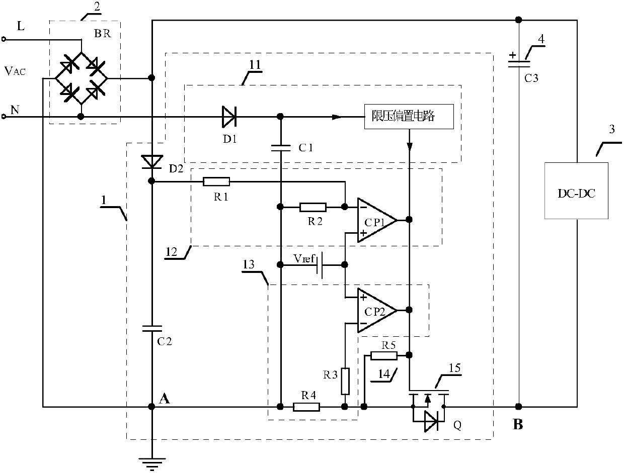
[0029] Please refer to figure 1 , figure 1 A schematic diagram of a specific implementation of an input overvoltage protection circuit with a power-on surge current suppression function provided by an embodiment of the present invention. The input overvoltage protection circuit 1 includes a power supply circuit 11, a peak detection circuit, and a peak voltage sampling comparison Circuit 12, switch tube current sampling comparison circuit 13 at the moment of power-on, fifth resistor 14, low on-resistance switch tube 15 and reference voltage source;

[0030] The power supply circuit 11 includes a first diode D1, a first capacitor C1 and a voltage limiting bias circuit; the peak detection circuit includes a second diode D2 and a second capacitor C2; the peak voltage sampling comparison circuit 12 includes a first comparator CP1 , the first resistor R1 and the second resistor R2; the switching tube current sampling comparison circuit 13 includes a second comparator CP2, a third r...

Embodiment 2

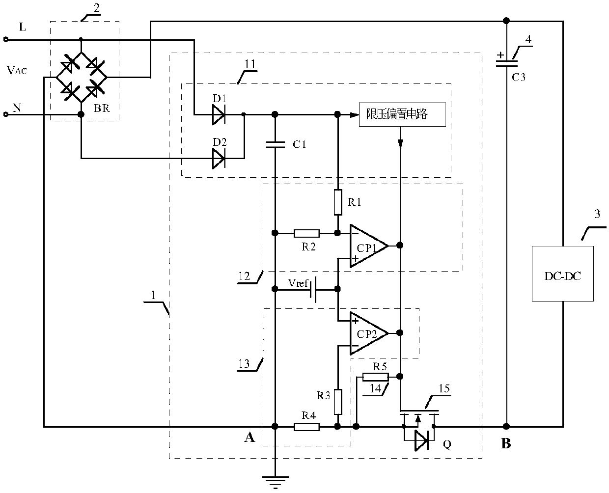
[0045] Based on the first embodiment above, see figure 2 Another schematic diagram of an input overvoltage protection circuit with a power-on surge current suppression function is shown. In this embodiment, a peak detection circuit is incorporated into a power supply circuit to obtain a peak detection power supply circuit; the peak detection power supply circuit includes a first diode D1 , the second diode D2, the voltage limiting bias circuit and the first capacitor C1; the anode of the first diode D1 is connected to the commercial power L terminal, and the negative electrode is respectively connected to the input terminal of the voltage limiting bias circuit and the first capacitor C1 One end of the second diode D2 is connected to the cathode; the anode of the second diode D2 is connected to the N terminal of the mains.

[0046] That is to say, compared with the first embodiment, the difference of this embodiment is that two rectifier diodes are provided in the power supply...

Embodiment 3

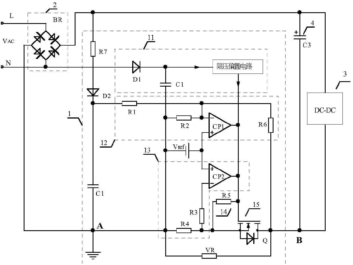
[0048] Based on any of the above embodiments, see image 3 Another schematic diagram of the input overvoltage protection circuit with power-on surge current suppression function shown, the input overvoltage protection circuit may also include a sixth resistor R6, one end of the sixth resistor R6 is connected to the first comparator CP1 The inverting input end is connected to the other end of the first resistor R1 , and the other end is connected to the third end of the low on-resistance switch tube 15 .

[0049] The inverting input terminal of the comparator CP1 is connected to the third terminal of the low on-resistance switch tube 15 to form a positive feedback path, which can prevent the low-on-resistance switch tube 15 from operating at the input voltage V IN The opening and closing phenomenon that may occur when it is near the overvoltage protection point. For example, when the input voltage V IN Just equal to the overvoltage protection voltage, the comparator CP1 outpu...


PUM


Abstract

The invention discloses an input overvoltage protection circuit with a powered inrush current restraining function. The input overvoltage protection circuit comprises a power supply circuit, a peak detection circuit, a peak voltage sampling comparison circuit, a powered moment switching tube current sampling comparison circuit, a bleeder resistor, a low on-resistance switching tube and a referencevoltage source; the power supply circuit comprises a first diode, a first capacitor and a voltage limiting biasing circuit; the peak detection circuit comprises a second diode and a second capacitor;the peak voltage sampling comparison circuit comprises a first comparator, a first resistor and a second resistor; and the powered moment switching pipe current sampling comparison circuit comprisesa second comparator, a third resistor and a fourth resistor. Therefore, the input overvoltage protection circuit is rapid in overvoltage protection action, and can restrain powered inrush current; theovervoltage protection circuit and the powered inrush current restraining circuit are organically combined to share a power switching tube and the power supply circuit, and thus the number of elements is small and the cost is low. The input overvoltage protection circuit not only solves the problem of input overvoltage protection difficulty, but also restrains the powered inrush current.

Description

technical field [0001] The invention relates to the technical field of switching power supplies, in particular to an input overvoltage protection circuit with a power-on surge current suppression function. Background technique [0002] At present, most DC-DC converter control chips provide overvoltage protection function. This function can force the converter to stop working when abnormal high voltage occurs in the power grid, but it cannot solve the problem of overvoltage of the input filter capacitor, nor can it solve the problem of the output of the APFC circuit. Filter capacitor overvoltage problem. For this reason, some converters add a mains detection circuit to trigger the relay action when the mains is abnormal, and disconnect the input circuit of the converter. However, the reliability of the electromagnetic relay is poor and the action is slow. The input filter capacitor still bears the instantaneous high voltage, which has not been completely solved. security ris...

Claims


Application Information

Patent Timeline
Patent Type & Authority Applications(China)
IPC IPC(8): H02H7/12H02H9/02
CPCH02H7/1213H02H9/02Y02B70/10
Inventor 潘永雄陈林海李勇蔡炳利
Owner GUANGDONG UNIV OF TECH
Why Eureka
Try Eureka