Fusing device

a technology of fusing device and fusing chamber, which is applied in the direction of electrographic process apparatus, instruments, optics, etc., can solve the problems of increasing the power of the heating source, increasing the required thermal amount per unit time, and increasing the required thermal amount. the effect of reducing the diameter of the roller and reducing the pressure required for fusing

Active Publication Date: 2005-09-01
OKI ELECTRIC IND CO LTD
View PDF3 Cites 24 Cited by
  • Summary
  • Abstract
  • Description
  • Claims
  • Application Information

AI Technical Summary

Benefits of technology

[0029] In the above case, the pushing member is disposed inside the fusing belt, as arranged together with and on the upstream side with respect to the roller in the driving direction of the fusing belt, and rendered in pressurized contact with the pressure member through the fusing belt, so that the contact area becomes larger. Therefore, since the diameter of the roller can be reduced, pressure required for fusing can be reduced.
[0030] As the result, the roller comes not to bend even in a case of having a small diameter, so that the nipping width becomes unified between the central portion and opposite ends in the longitudinal direction of the roller, and thus defective fusing can be prevented from occurring.

Problems solved by technology

Where the fusing device of this heating roller type is applied to a multicolor printer, a predetermined thermal amount is required to fuse the toner image, and because the toner images in multiple colors need to be overlaid on the sheet to form the multicolored image, a required thermal amount undesirably increases by that much.
Furthermore, where the fusing device of the heating roller type is applied to a high speed printer, since the toner image is fused at a high speed, a required thermal amount per unit time further increases compared with a case where the toner image is fused at a low speed.
Furthermore, to fuse the toner image at high speed, it is required to increase the power of the heating source or to widen the nipping width by an amount corresponding to shortening of time.
With the conventional fusing device, however, in a case of a small diameter of the fusing roller 14, the fusing roller 14 bends, thereby causing a difference in the nipping width between a central portion and opposite ends in a longitudinal direction of the fusing roller 14, so that defective fusing comes to easily occur.
It is conceivable to reduce hardness of the elastic layer 14a to widen the nipping width by that much, however, in that case it become impossible to pressure sufficiently the toner image 20 in which the toner layers are overlaid, so that the defective fusing easily occurs as well.

Method used


Image

  • Fusing device
  • Fusing device
  • Fusing device

Examples


first embodiment

[0068]FIG. 7 is a chart showing pressure distribution inside a nipping area according to this invention. In FIG. 7, it is to be noted that an abscissa indicates a position on the nipping area N while an ordinate indicates the pressure.

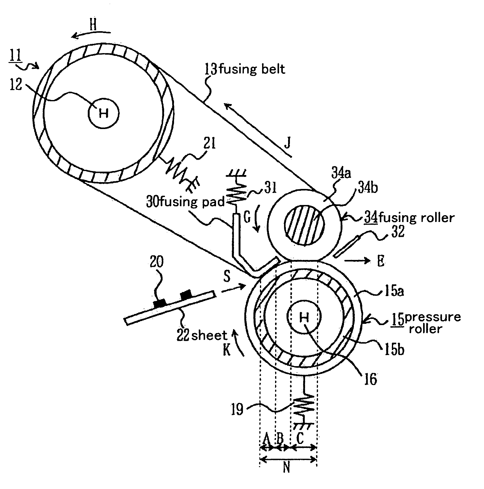
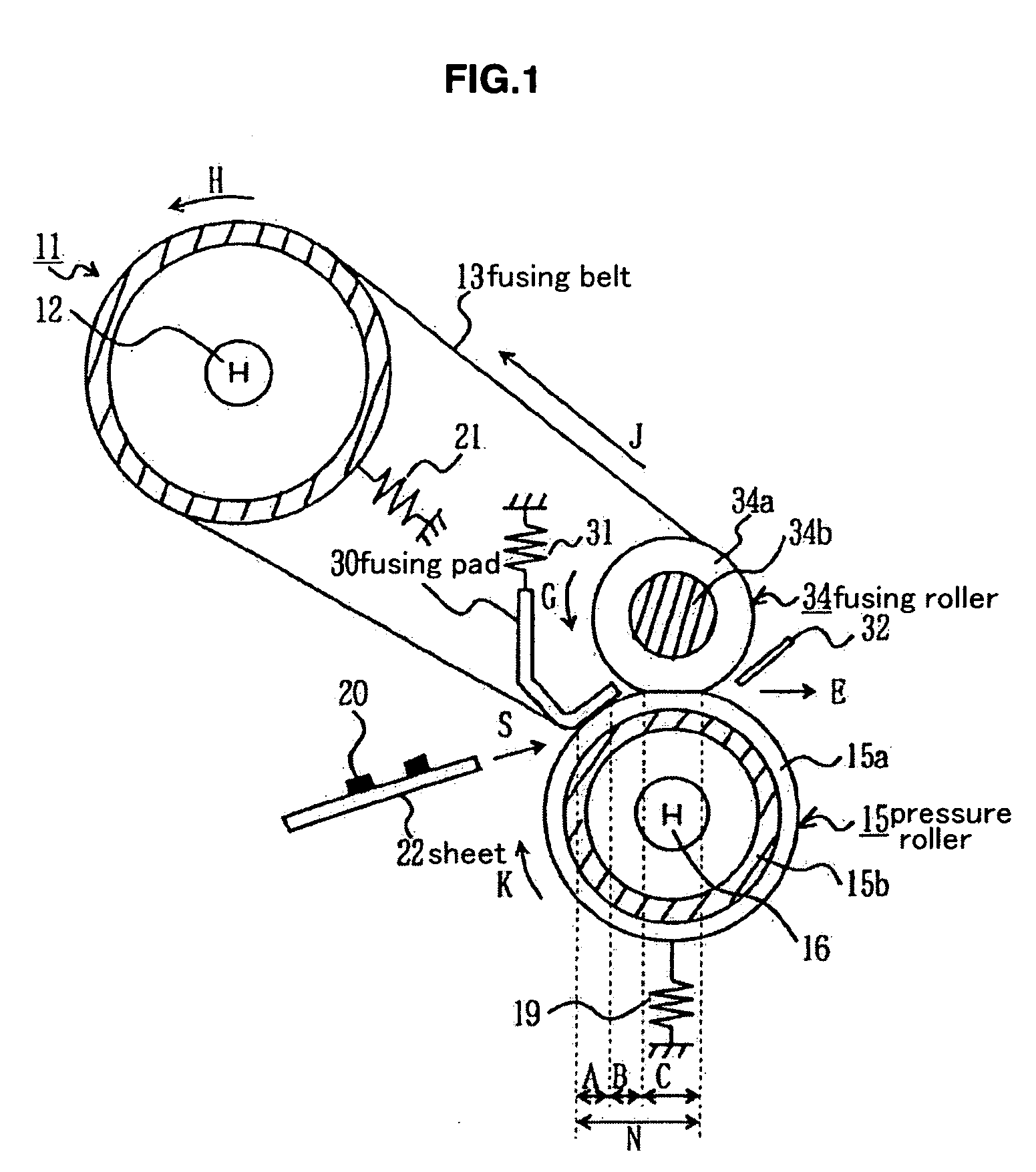
[0069] First, the heaters 12 (in FIG. 1), 16 generate heat to heat up the heating roller 11 and the pressure roller 15. The fusing roller 34 is next rendered to rotate in the direction of the arrow G by a driving motor, not show, so that the fusing belt 13 is rendered to drive in the direction of the arrow J in accordance with the fusing roller 34; the heating roller 11 is driven to rotate in the direction of the arrow H in accordance with the fusing belt 13; and the pressure roller 15 is driven to rotate in the direction of the arrow K in accordance with the fusing belt 13.

[0070] When the temperature of the fusing belt 13 heated with the heating roller 11 and the pressure roller 15 reaches the set fusing temperature, the sheet 22 is conveyed in the d...

fourth embodiment

[0094] In the meantime, in the fourth embodiment, torque of the motor, i.e., motor torque required for rotating the fusing roller 34 undesirably increases. Thus, if the torque of the motor is made smaller, the front end portion of the fusing pad 40 needs to be sharpened, thereby resulting in the thin thickness. Furthermore, because the fusing pad 40 is formed of, e.g., a metal, when the thickness of the front end portion is thinned, the front end portion easily gets deformed in a plastic manner, so that durability of the fusing device may be deteriorated. Where the front end portion of the fusing pad 40 is plastically deformed, the pressure distribution inside the nipping area N changes, thereby causing defective fusing to easily occurs.

[0095] Herein, the fifth embodiment will be explained, in which the torque of the motor for rotating the fusing roller 34 can be reduced, the durability of the fusing device can be enhanced, and the occurrence of the defective fusing can be prevented...

fifth embodiment

[0096]FIG. 14 is a cross-sectional view showing a fusing device of a belt type according to this invention.

[0097] As shown in FIG. 14, a fusing pad 45 defined as the pushing member has the base portion 45a equipped with the spring 31 serving as the second urging member and a pressurized contact portion 45b extending from a lower end of the base portion 45a toward the pressure roller 15 serving as the pressure member as well as the second roller, and a portion of the pressurized contact portion 45b, at which the fusing pad is rendered in pressurized contact with the pressure roller 15 through the fusing belt 13, is disposed with a distance from the area C.

[0098] To prevent a front end of the fusing pad 45 from plastically deformed, the fusing pad 45 is equipped with a leaf spring 46 serving as the pressurized contact member and serving as a plate shaped member. The leaf spring 46 is formed of a metal such as, e.g., stainless steel, or the like, and has a base portion 46a equipped wi...


PUM


Abstract

To prevent a defective fusing from occurring, a fusing member has a roller; a fusing belt heated and rendered to drive along a circumference of the roller; a pressure member disposed outside the fusing belt and rendered in pressurized contact with the roller through the fusing belt; and a pushing member disposed inside the fusing belt, as arranged together with and at an upstream side from the roller in a driving direction of the fusing belt, and rendered in pressurized contact with the pressure member through the fusing belt. The fusing belt and the pressure member compose a contact area for allowing a recording medium to pass through. The pushing member is disposed inside the fusing belt as arranged together with and on an upstream side with respect to the roller in a driving direction of the fusing belt, so that the contact becomes wider.

Description

BACKGROUND OF THE INVENTION [0001] 1. Field of the Invention [0002] This invention relates to a fusing device. [0003] 2. Description of Related Art [0004] A fusing device in an image forming apparatus such as, e.g., a printer, a photocopier, a printing apparatus, or the like, for example, a fusing device of a printer, conventionally has a fusing roller installed inside with a heating source, and a pressure roller driven to rotate in pressurized contact with the fusing roller, and in such a fusing device, a sheet carrying a toner image not yet fused is transmitted to a nipping area formed between the fusing roller and the pressure roller to fuse the toner image onto the sheet at the nipping area. [0005] Where the fusing device of this heating roller type is applied to a multicolor printer, a predetermined thermal amount is required to fuse the toner image, and because the toner images in multiple colors need to be overlaid on the sheet to form the multicolored image, a required therm...

Claims


Application Information

Patent Timeline
Patent Type & Authority Applications(United States)
IPC IPC(8): G03G15/20
CPCG03G2215/2009G03G2215/2022G03G15/2064G03G15/2053
Inventor YOSHIDA, TATSUHOOISHI, NOBORU
Owner OKI ELECTRIC IND CO LTD
Why Eureka
Try Eureka