
Liquid crystal display and method for manufacturing the same

a technology of liquid crystal display and liquid crystal, which is applied in the manufacture of electrode systems, electric discharge tubes/lamps, instruments, etc., can solve the problems of reducing production yields and sensitivity, and achieve the effect of reducing weight and thickness, and simplifying touch detection

Inactive Publication Date: 2012-08-23
SAMSUNG DISPLAY CO LTD
View PDF3 Cites 22 Cited by
  • Summary
  • Abstract
  • Description
  • Claims
  • Application Information

AI Technical Summary

Benefits of technology

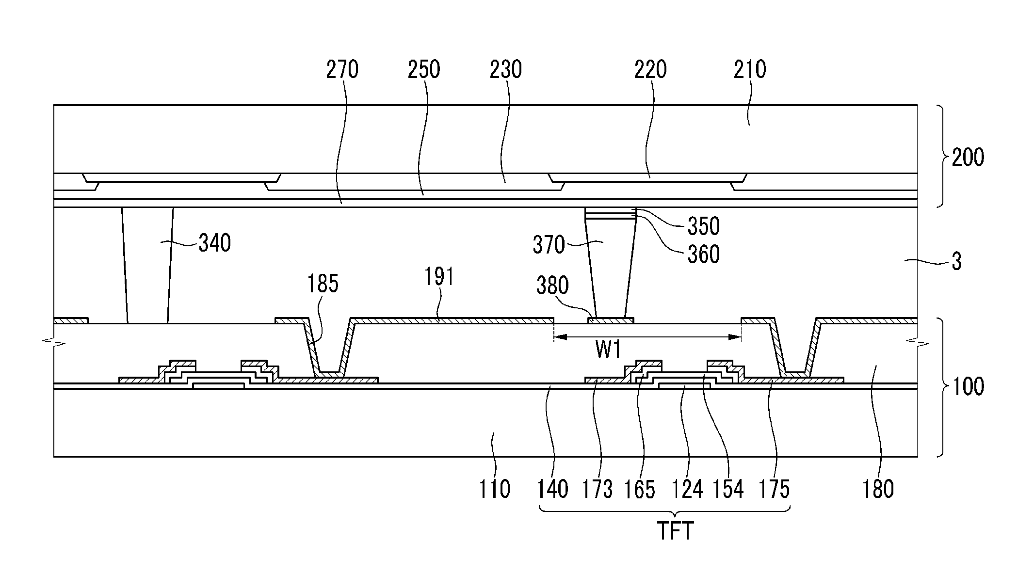
[0016]The resistance of the sensing spacer may be reduced when an external force is applied to the second display panel, resulting in current flow between the upper resistive layer and the lower resistive layer.
[0026]The resistance of the pressure sensing layer may be reduced when an external force is applied to the second display panel, such that current flows between the first resistive layer and the second resistive layer.
[0038]According to an exemplary embodiment of the present invention, a variable touch display may be realized, such that expression according to intensity of an applied pressure is possible, as well simplified touch detection. A touch function is provided in a liquid crystal display, and thereby the weight and thickness thereof may be reduced.

Problems solved by technology

However, the sensitivity is decreased according to the size of the gap and / or production yields may be decreased by deterioration of the products.

Method used


Image

  • Liquid crystal display and method for manufacturing the same
  • Liquid crystal display and method for manufacturing the same
  • Liquid crystal display and method for manufacturing the same

Examples


Embodiment Construction

[0050]The invention is described more fully hereinafter with reference to the accompanying drawings, in which exemplary embodiments of the invention are shown. This invention may, however, be embodied in many different forms and should not be construed as limited to the exemplary embodiments set forth herein. Rather, these exemplary embodiments are provided so that this disclosure is thorough, and will fully convey the scope of the invention to those skilled in the art. In the drawings, the size and relative sizes of layers and regions may be exaggerated for clarity. Like reference numerals in the drawings denote like elements.

[0051]It will be understood that when an element or layer is referred to as being “on” or “connected to” another element or layer, it can be directly on or directly connected to the other element or layer, or intervening elements or layers may be present. In contrast, when an element is referred to as being “directly on” or “directly connected to” another elem...


PUM

PropertyMeasurementUnit
resistanceaaaaaaaaaa
external forceaaaaaaaaaa
resistanceaaaaaaaaaa

Abstract

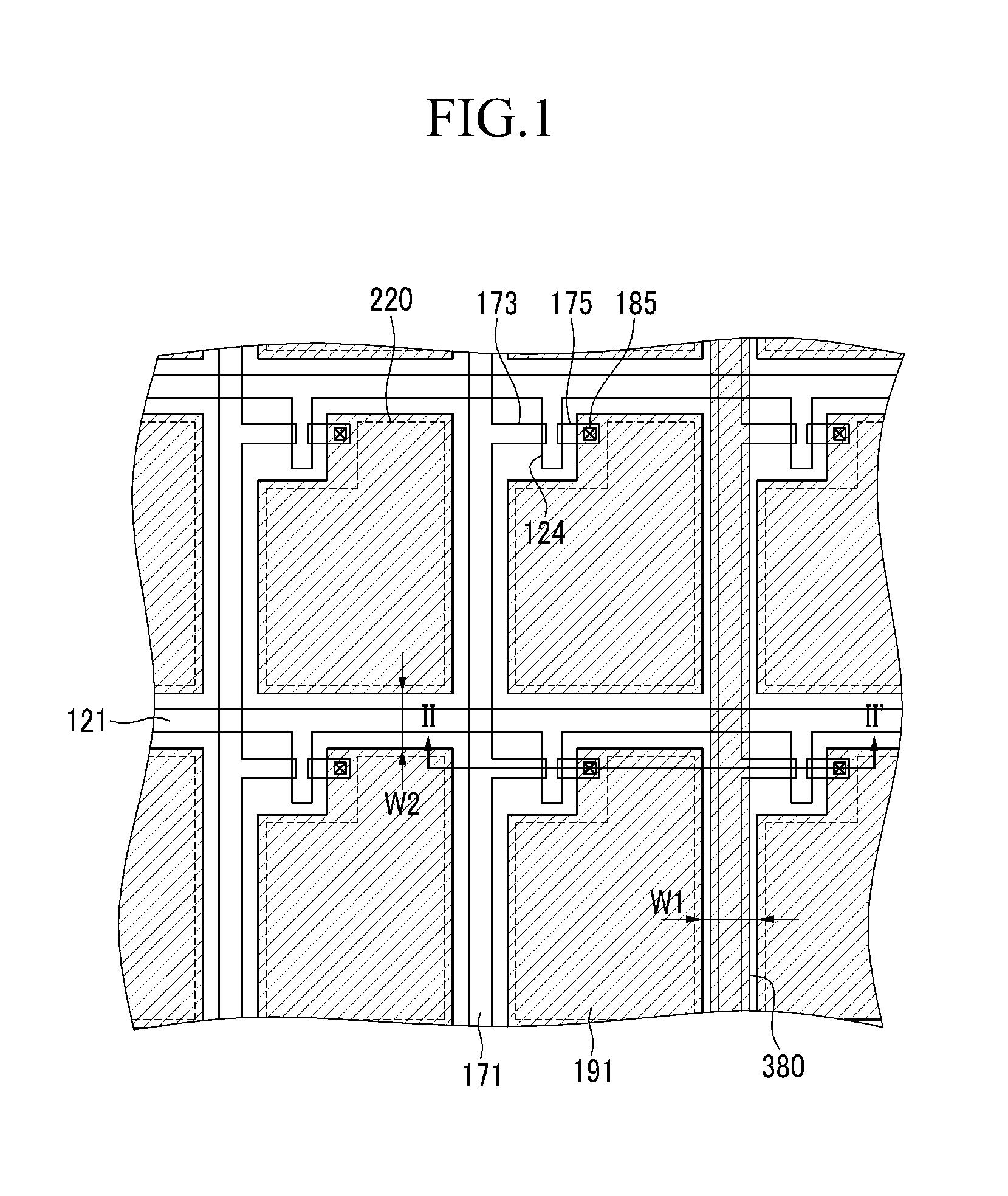
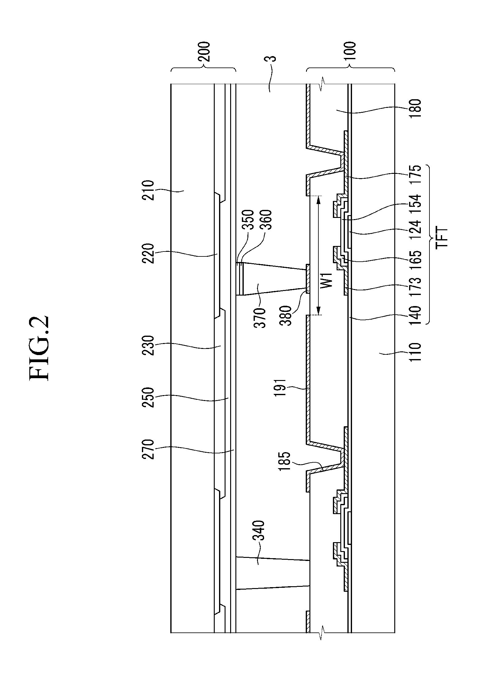
A liquid crystal display is provided that includes: a first display panel including a thin film transistor and a plurality of pixel electrodes; a second display panel facing the first display panel with a cell gap therebetween; a lower resistive layer disposed on the first display panel; an upper resistive layer disposed on the second display panel; and a sensing spacer connecting the lower resistive layer and the upper resistive layer.

Description

CROSS-REFERENCE TO RELATED APPLICATION[0001]This application claims priority to and the benefit of Korean Patent Application No. 10-2011-0014673, filed on Feb. 18, 2011, which is hereby incorporated by reference for all purposes as if fully set forth herein.BACKGROUND OF THE INVENTION[0002]1. Field of the Invention[0003]Exemplary embodiments of the present invention relate to a liquid crystal display and a manufacturing method thereof.[0004]2. Discussion of the Background[0005]Liquid crystal displays are now one of the most widely used type of flat panel display. A liquid crystal display has two display panels, on which field generating electrodes such as pixel electrodes and a common electrode are formed. A liquid crystal layer is interposed between the display panels. In the liquid crystal display, a voltage is applied to the field generating electrodes, so as to form an electric field in the liquid crystal layer. The alignment of liquid crystal molecules of the liquid crystal lay...

Claims


Application Information

Patent Timeline
Patent Type & Authority Applications(United States)
IPC IPC(8): G02F1/1339H01J9/24
CPCG06F3/0412G02F1/13394G06F3/047G02F1/133308G02F1/13338G06F3/0414G06F3/045G06F2203/04103G02F1/133512G02F1/133514G02F1/1339G02F1/1368
Inventor HWANG, SEONG MOJANG, HYEON YONGPYUN, JAE JINLEE, IL HOBAEK, MOON JUNG
Owner SAMSUNG DISPLAY CO LTD
Learn More