Linear spring electromagnetic grill ink jet printing mechanism

a technology of electromagnetic grille and ink jet printing mechanism, which is applied in the field of shuttered grille ink jet printer, to achieve the effect of reducing the pressure requirement of the ink jet reservoir and restricting the backflow of ink

Inactive Publication Date: 2001-07-24
SILVERBROOK RES PTY LTD +1
View PDF4 Cites 22 Cited by
  • Summary
  • Abstract
  • Description
  • Claims
  • Application Information

AI Technical Summary

Benefits of technology

In accordance with the second aspect of the present invention there is provided a shuttered ink jet nozzle comprising an ink chamber having an ink ejection nozzle for the ejection of ink from the ink chamber, an ink reservoir for the supply of ink to the ink chamber under pressure, and a shutter device located between the ink reservoir and the ink chamber so as to allow or restrict the flow of ink between the ink chamber and ink reservoir to thereby cause the ejection of ink from the chamber, wherein the shutter device is being actuated on demand.
Further the actuator comprises an electromagnetic coil mechanism attracting a magnetic bar. Preferably the coil is anchored to a wafer and the magnetic bar is connected to a shutter plate adapted to open and close over a series of shutter holes allowing fluid communication between the ink reservoir and the ink chamber. Advantageously the shuttered ink jet nozzle comprises an actuator that includes at least one linear spring so as to amplify the travel of a shutter plate covering shutter holes upon activation of the actuator. The linear spring is anchored on one side of the ink chamber and the electromagnetic coil is anchored to an opposite side of the ink chamber with a shutter plate operable between the linear spring anchor and the electromagnetic anchor. Preferably the ink reservoir includes ink under an oscillating ink pressure. The shutter device comprises a plurality of shutter plates covering a corresponding plurality of shutter holes allowing the flow of ink between the ink chamber and the ink reservoir. Further the ink chamber is formed by a crystallographic etch of a silicon wafer. The ejection frequency of drops from the nozzle chamber is substantially half the frequency of an oscillating pressure of the ink within the ink reservoir. Advantageously, arrays of ink jet nozzles are grooved into face grooves and each face groove is activated in turn so as to reduce pressure requirements in an ink jet reservoir.
In accordance with the third aspect of the present invention there is provided a method of operation of a shuttered ink jet print nozzle having a nozzle chamber and ink reservoir, the ink reservoir having an oscillating ink pressure, comprising opening the shutter to cause ink to be ejected from the nozzle chamber resulting in a reduction of ink in the nozzle chamber, following by leaving the shutter open during a subsequent high pressure of the ink pressure so as to allow the nozzle chamber to refill, followed by closing the shutter at the end of a high pressure cycle so as to restrict back flow of ink from the nozzle chamber to the ink reservoir.

Problems solved by technology

Each technology may have its own advantages and disadvantages in the areas of cost, speed, quality, reliability, power usage, simplicity of construction operation, durability and consumables.

Method used


Image

  • Linear spring electromagnetic grill ink jet printing mechanism
  • Linear spring electromagnetic grill ink jet printing mechanism
  • Linear spring electromagnetic grill ink jet printing mechanism

Examples


Embodiment Construction

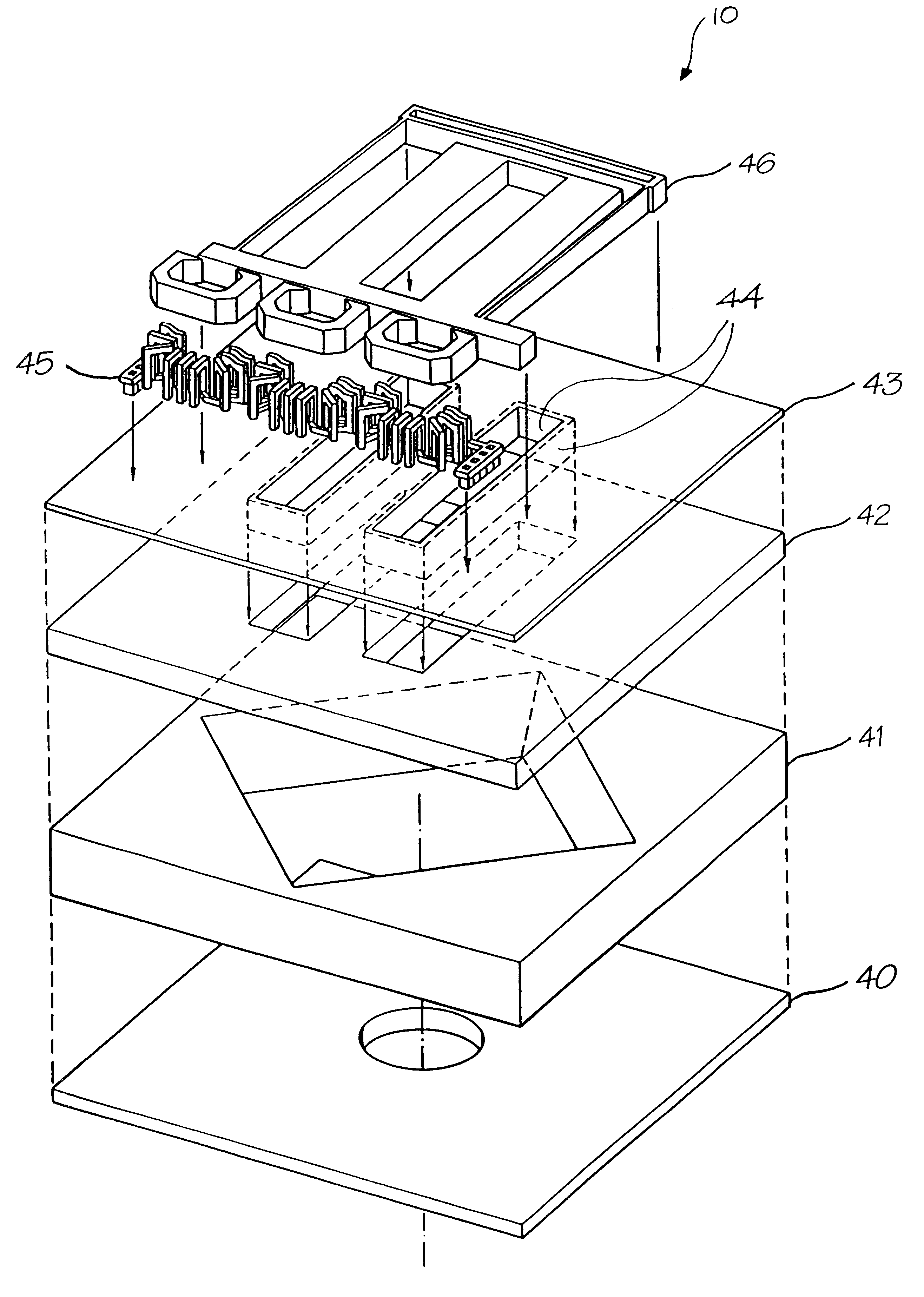
In the present invention, a magnetically actuated ink jet print nozzle is provided for the ejection of ink from an ink chamber. The magnetically actuated ink jet utilises utilizes a linear spring to increase the travel of a shutter grill which blocks any ink pressure variations in a nozzle when in a closed position. However when the shutter is open, pressure variations are directly transmitted to the nozzle chamber and can result in the ejection of ink from the chamber. An oscillating ink pressure within an ink reservoir is used therefore to eject ink from nozzles having an open shutter grill.

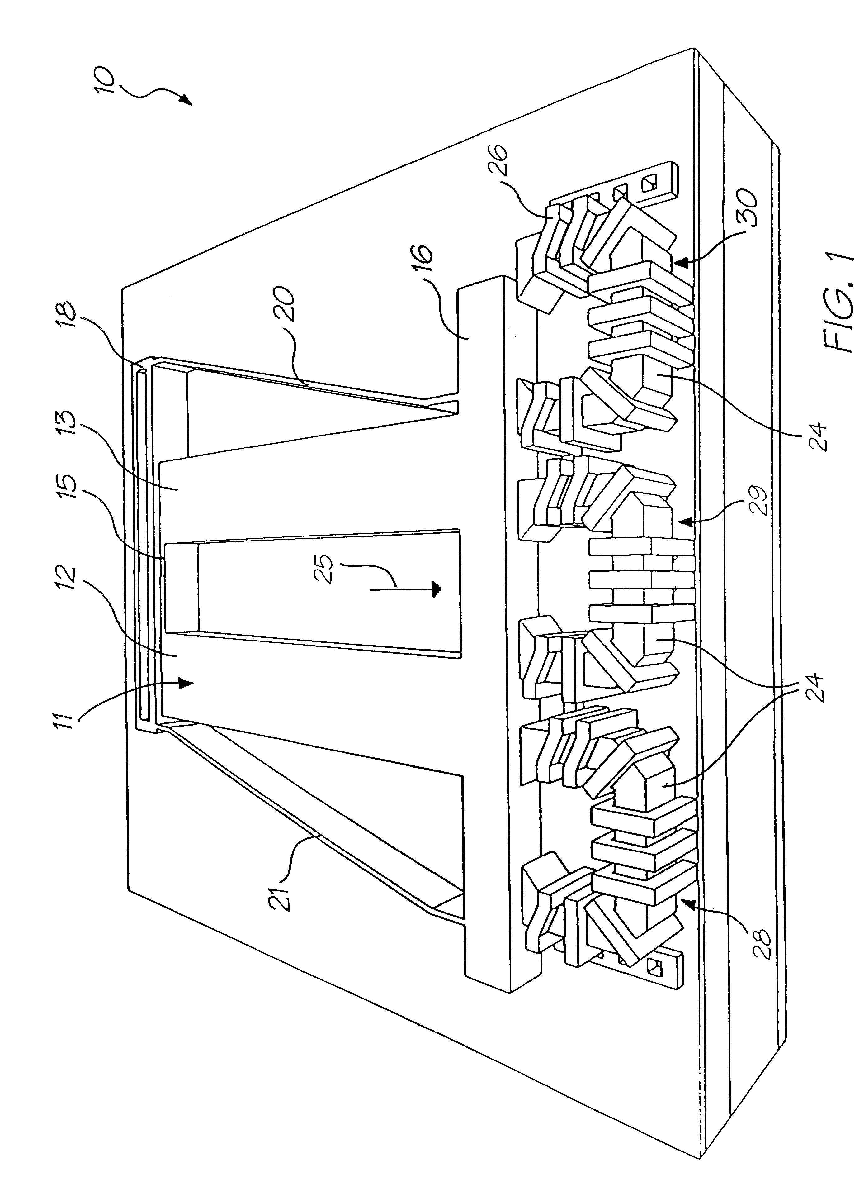
In FIG. 1, there is illustrated a single nozzle mechanism 10 of the preferred embodiment when in a closed or rest position. The arrangement 10 includes a shutter mechanism 11 having shutters 12, 13 which are interconnected together by part 15 at one end for providing structural stability. The two shutters 12, 13 are interconnected at another end to a moveable bar 16 which is further connected t...


PUM


Abstract

This patent describes a shuttered ink jet nozzle having a shutter located between the ink reservoir and an ink chamber so as to allow or restrict the flow of ink between the ink chamber and ink reservoir to thereby cause the ejection of ink from the. chamber, the shutter being actuated on demand. The shutter can an electromagnetic coil mechanism attracting a magnetic plate. The coil is anchored to a wafer and the magnetic plate is connected to a shutter plate and adapted to open and close over a series of shutter holes allowing fluid communication between the ink reservoir and the ink chamber. The actuator can include linear springs so as to amplify the travel of a shutter plate covering shutter holes upon activation of the actuator. The ink reservoir includes ink under an oscillating ink pressure which is ejected from the nozzle chamber when the shutters are in an open position. An array of ink jet nozzles can be constructed and grouped into phase groups and each phase group is activated in turn so as to reduce pressure requirements in an ink jet reservoir. The shutters can be used to cause ink to be ejected from the nozzle chamber, followed by leaving the shutter open during a subsequent high pressure period to allow rapid refill, followed by closing the shutter at the end of a high pressure cycle so as to restrict back flow of ink from the nozzle chamber to the ink reservoir.

Description

The following Australian provisional patent applications are hereby incorporated by cross-reference. For the purposes of location and identification, U.S. patent applications identified by their U.S. patent application serial numbers (U.S.S.N.) are listed alongside the Australian applications from which the U.S. patent applications claim the right of priority.Not applicable.The present invention relates to ink jet printing and in particular discloses a linear Spring Electromagnetic Grill hik Jet Printer.The present invention fiuther relates to the field of drop on demand ink jet printing.Many different types of printing have been invented, a large number of which are presently in use. The known forms of print have a variety of methods for marking the print media with a relevant marking media. Commonly used forms of printing include offset printing, laser printing and copyirg devices, dot matrix type impact printers, thermal paper printers, film recorders, thermal wax printers, dye s...

Claims


Application Information

Patent Timeline
Patent Type & Authority Patents(United States)
IPC IPC(8): B41J2/045B41J11/70B41J2/14B41J15/04B41J2/16B42D15/10B41J3/42B41J11/00G06F1/16G06K1/12G07F7/12G06K1/00G06K19/073G06K19/06G06K7/14G11C11/56G07F7/08H04N1/32H04N5/262H04N5/225H04N1/21B41J2/175B41J2/165H04N1/00B41J3/44
CPCB41J2/14427H04N5/2628B41J2/1628B41J2/1629B41J2/1631B41J2/1632B41J2/1635B41J2/1639B41J2/1642B41J2/1643B41J2/1645B41J2/1646B41J2/1648B41J3/445B41J11/0005B41J11/70B41J15/04B82Y30/00G06K1/121G06K7/14G06K7/1417G06K19/06037G11C11/56H04N5/225B41J2/1623B41J2/16585B41J2/17596B41J2002/041B41J2002/14346H04N23/00
Inventor SILVERBROOK, KIA
Owner SILVERBROOK RES PTY LTD
Why Eureka
Try Eureka