
Cold fuel cooling of intercooler and aftercooler

a technology of intercooler and cold fuel, which is applied in the direction of machine/engine, combustion-air/fuel-air treatment, turbine/propulsion fuel heating, etc., to achieve the effect of reducing the corrected mass flow, reducing the power needs and/or the size and weight of the engine, and reducing the pressure required

Active Publication Date: 2010-08-05
AEROVIRONMENT INC
View PDF28 Cites 24 Cited by
  • Summary
  • Abstract
  • Description
  • Claims
  • Application Information

AI Technical Summary

Benefits of technology

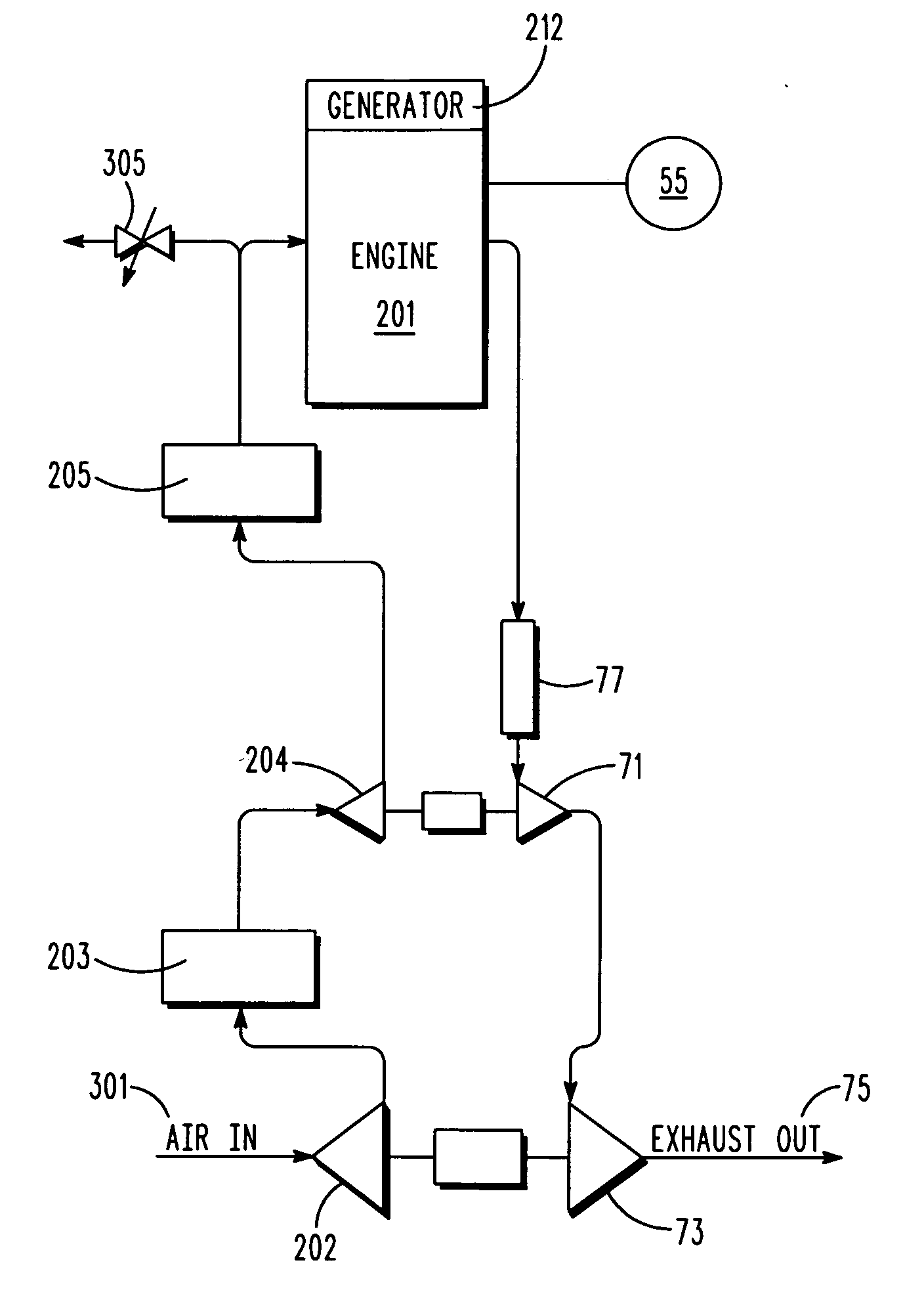
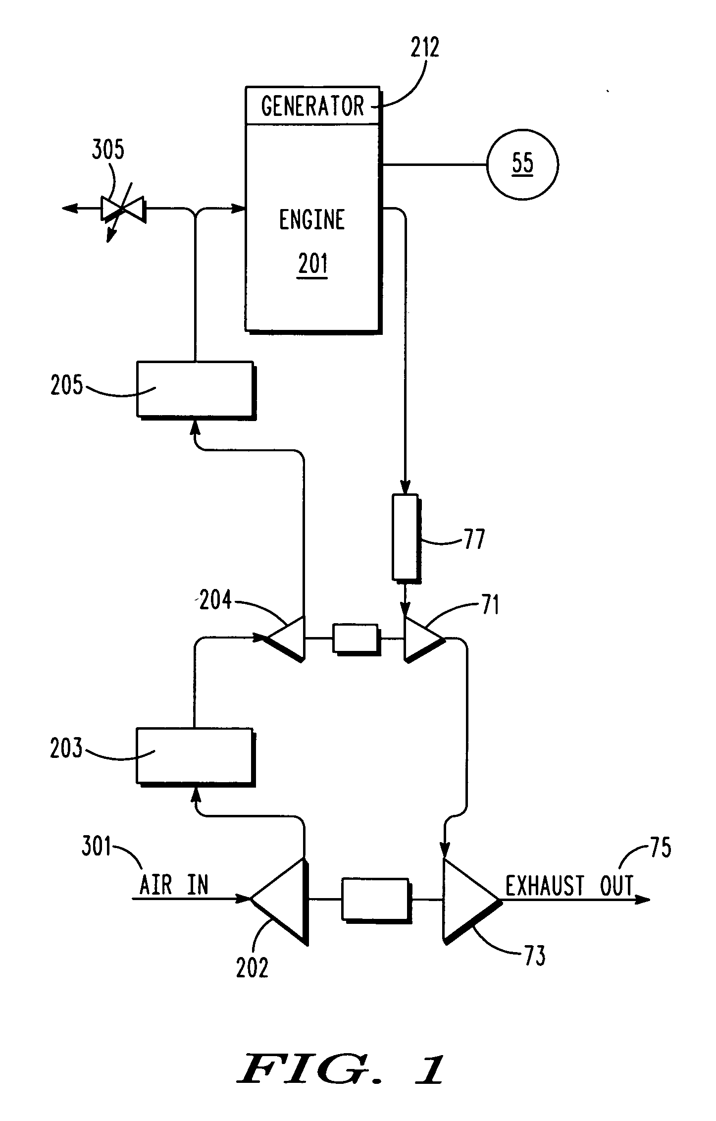
[0011]One way to efficiently achieve better intercooler and aftercooler cooling is by using a colder coolant. Advantageously, the first-compressor heat exchanger is configured to use the coolant at the sub-ambient temperature from the fuel heat exchanger to cool the oxidizer intermediate the first compressor and the power converter along the oxidizer flow path. This provides for a reduction in the power consumed by the air compression system for a high altitude engine, such as one that burns hydrogen gas that is boiled off from a liquid hydrogen tank. Moreover, if a subsequent high-pressure compressor is also used, the colder air will reduce its corrected mass flow, reducing its power needs and / or its size and weight. Thus there is a unique synergy between the cooling needs of an intercooler and the warming needs of the hydrogen fuel.
[0012]The powerplant typically further includes a second compressor intermediate the first-compressor heat exchanger and the power converter, along the flow path of the oxidizer. The second compressor is configured to further compress oxidizer from first-compressor heat exchanger prior to use by the power converter. A second-compressor heat exchanger is also configured to use the coolant from the fuel heat exchanger at the sub-ambient temperature. It cools the oxidizer intermediate the second compressor and the power converter along a flow path of the oxidizer. This reduces the pressure required to achieve the desired density of air fed to the engine, and thereby reduces the compression work required. Thus there is a unique synergy between the cooling needs of an aftercooler and the warming needs of the hydrogen fuel.
[0013]To aid in lowering the temperature of the coolant, a ram-air heat exchanger upstream of the fuel heat exchanger is configured to cool the coolant to a temperature that is just above ambient temperature.
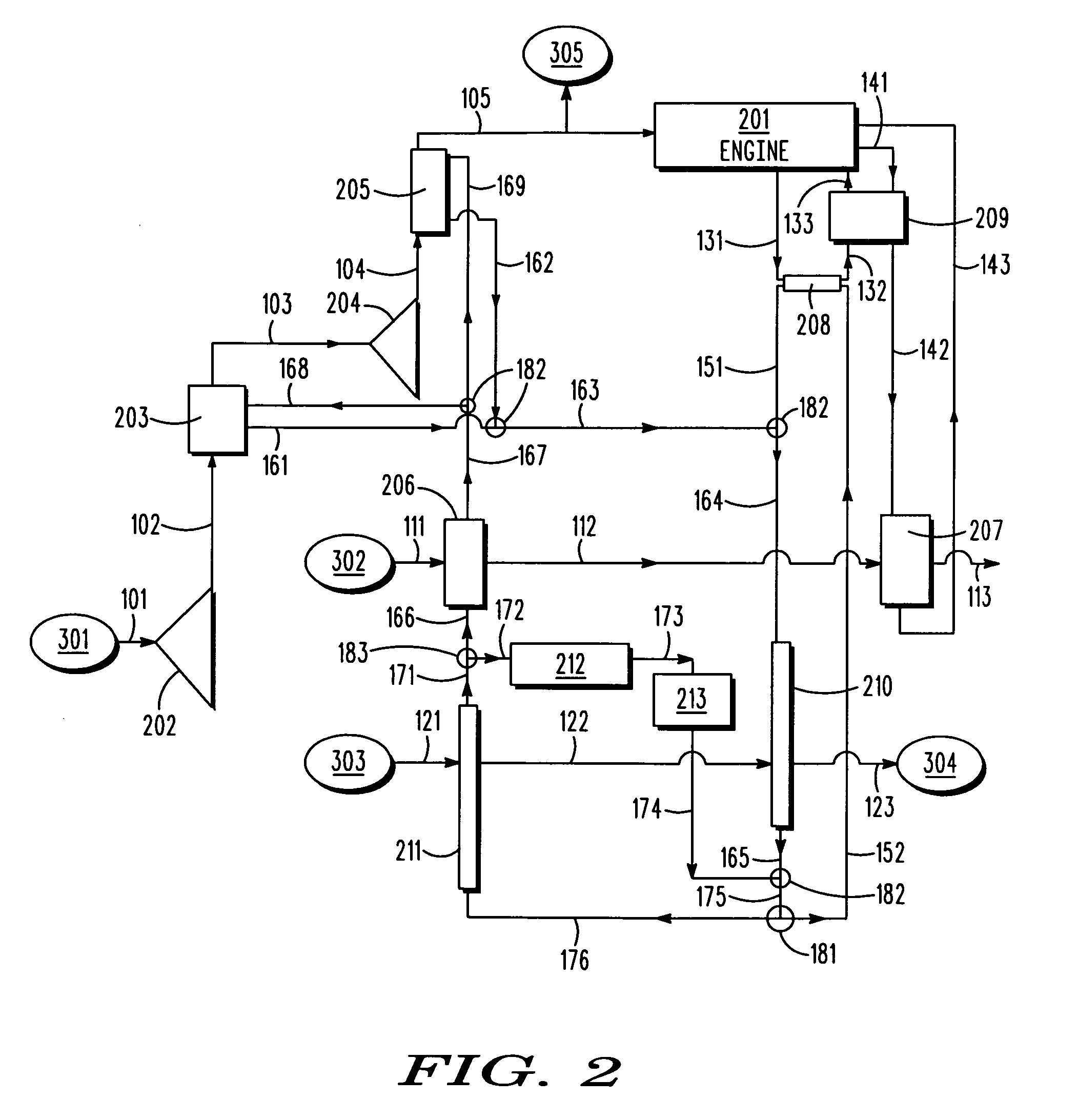
[0015]The cooling system includes three cooling loops with thermal loads. These three loops respectively incorporate only the front portion, only the rear portion, and both portions of the ram-air cooler. Advantageously, this efficiently allows for the heat sinks and sources to operate in their best temperature ranges, while sharing the work for coolant flows of a similar temperature.

Problems solved by technology

Moreover, if a subsequent high-pressure compressor is also used, the colder air will reduce its corrected mass flow, reducing its power needs and / or its size and weight.
This reduces the pressure required to achieve the desired density of air fed to the engine, and thereby reduces the compression work required.

Method used


Image

  • Cold fuel cooling of intercooler and aftercooler
  • Cold fuel cooling of intercooler and aftercooler
  • Cold fuel cooling of intercooler and aftercooler

Examples


first embodiment

[0029]With reference to FIG. 1, the powerplant of the first embodiment includes a power generation system including an internal combustion piston engine 201 that drives a generator 212. In alternative embodiments the power generator could be an engine that directly drives a mechanical system such as a propeller system, or a fuel cell. The powerplant also includes a control system 55 configured to control the operation of the powerplant over an envelope of operating conditions (e.g., over a range of power generation requirements), over a range of operating conditions (e.g., temperatures and pressures throughout the powerplant), and over a range of ambient conditions that can range from sea-level temperatures and pressures to stratospheric conditions.

[0030]As an oxidizer, the engine uses ambient air received in a first air scoop 301, and that is first compressed in a first-turbocharger compressor 202 and cooled in an intercooler 203, and then compressed in a second-turbocharger compre...

fourth embodiment

[0057]In the invention, the second hydrogen heater is integrated into the primary cooling network, and the third cooling network is thermally isolated from both the primary cooling network and the second cooling network. More particularly, with reference to FIG. 4, the second hydrogen heater 207 is integrated into the rear-ram-air heat exchanger input passageway 164, and is thereby adapted to use hydrogen that has been once cooled by the first hydrogen heater 206 to cool coolant from the intercooler 203, the aftercooler 205, and the engine-coolant heat exchanger 208. Additionally, the coolant-oil heat exchanger 209 has been eliminated. Also, a bypass 191 has been provided to allow adequate hydrogen heating at the first hydrogen heater 206 when the intercooler 203 and aftercooler 205 only require a slow flow of coolant.

fifth embodiment

[0058]With reference to FIG. 5, in the invention, a highly cooled payload device 214 such as a low temperature sensor requires cooling using a below-ambient temperature cooling fluid. The ultra-chilled compressor-cooler coolant passageway 167 becomes the split-off point for a separate coolant loop that passes ultra-chilled compressor-cooler coolant through the highly cooled payload device 214, which includes an integral heat exchanger configured to cool the device, and then back into the existing passageways at some temperature-appropriate passageway location, such as the hot compressor-cooler passageway 163. In a variation of this embodiment, the separate coolant loop passes ultra-chilled compressor-cooler coolant through the highly cooled payload device 214, and then back into the existing passageways at a cooler location, such as the once-heated additional-source passageway 173 (see FIG. 6).

Some Aspects of the Embodiment

[0059]With respect to FIGS. 1-6, the first hydrogen heater 2...


PUM


Abstract

A high-altitude aircraft powerplant including an engine, a two-stage turbocharger having an intercooler and an aftercooler, a cryogenic hydrogen fuel source, and a cooling system including a hydrogen heat exchanger. Aided by a ram-air cooler that cools a coolant to a near-ambient temperature, the heat exchanger is configured to heat the hydrogen using the coolant, and to cool the coolant to a temperature well below the ambient temperature during high-altitude flight. The intercooler and aftercooler use the sub-ambient temperature coolant, as does a separate sensor. The ram-air cooler includes a front portion and a rear portion. The cooling system includes three cooling loops which respectively incorporate only the front portion, only the rear portion, and both portions of the ram-air cooler.

Description

[0001]This application claims the benefit of U.S. provisional Application No. 61 / 194,103, filed Sep. 23, 2008, which is incorporated herein by reference for all purposes.[0002]The present invention relates generally to an aircraft powerplant thermal management systems and, more particularly, to an aircraft powerplant configured to use a vaporized cryogenic liquid fuel to cool various components using below-ambient temperature coolant.BACKGROUND OF THE INVENTION[0003]Aircraft powerplants typically need to consume ambient air for the oxygen to react with the hydrogen fuel. At high altitude, air is very low in pressure and density, and must typically be compressed in order to be usable in a powerplant. The power required for this compression can be a significant fraction of the gross output power of the powerplant, so it is important to minimize the power needed for compression so as to minimize the impact on overall system efficiency.[0004]Air pressurization for internal combustion en...

Claims


Application Information

Patent Timeline
Patent Type & Authority Applications(United States)
IPC IPC(8): F02B43/00F02M31/20F02M31/02F01P9/00
CPCF01P2050/20F05D2260/205F01P2060/10F02B29/0412F02B29/0493F02C6/12F02C7/143F02C7/16F02C7/224F02M31/16Y02T10/146Y02T50/675Y02T10/126F02B43/00F02M31/02F02M31/20F01P2060/02Y02T10/12Y02T50/60B60H1/00
Inventor BROOKS, ALEXANDER NELSONDALEY, JAMES GALLAGHERHIBBS, BART DEAN
Owner AEROVIRONMENT INC
Learn More