
Object-based virtual image drawing method of three-dimensional/free viewpoint television

A virtual image and object technology, applied in the field of virtual image drawing, can solve the problem of high computational complexity

Inactive Publication Date: 2010-04-14
上海贵知知识产权服务有限公司
View PDF0 Cites 11 Cited by
  • Summary
  • Abstract
  • Description
  • Claims
  • Application Information

AI Technical Summary

Problems solved by technology

Existing virtual image rendering algorithms based on depth images generally use the mapping method of 3D image warping pixel by pixel to ensure the accuracy of rendering, so the calculation complexity is too high, and there are still certain difficulties in meeting the real-time viewing requirements

Method used


Image

  • Object-based virtual image drawing method of three-dimensional/free viewpoint television
  • Object-based virtual image drawing method of three-dimensional/free viewpoint television
  • Object-based virtual image drawing method of three-dimensional/free viewpoint television

Examples


Embodiment 1

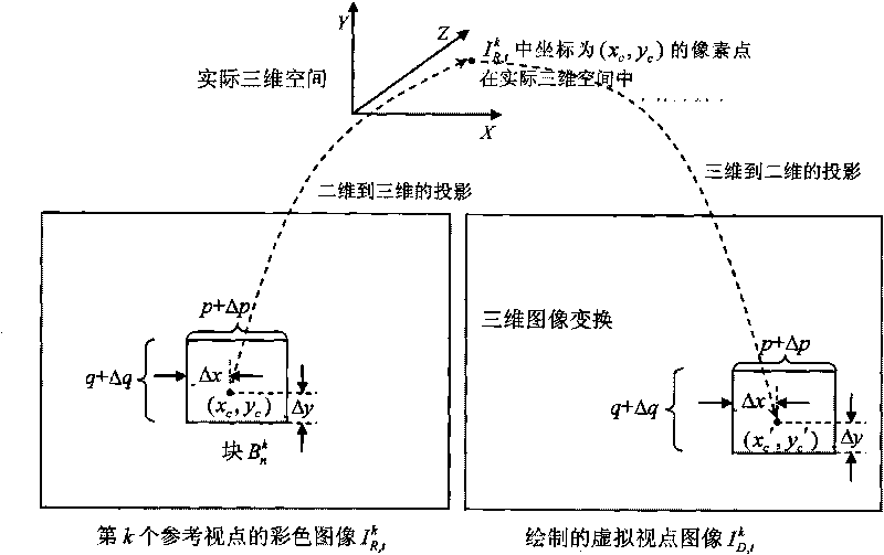
[0036] Embodiment one: a kind of object-based stereoscopic / free viewpoint TV virtual image rendering method of the present invention comprises the following specific steps:

[0037] ① Obtain K color images of K reference viewpoints with a size of P×Q and their corresponding K depth images at time t, and record the color image of the kth reference viewpoint at time t as I R,t k , denote the depth image of the kth reference viewpoint at time t as D R,t k , the color image I of the kth reference viewpoint at time t R,t k Adaptively divided into N R k A block whose size is (p+Δp)×(q+Δq), and mark the block mapping type of each block, record the color image I of the kth reference viewpoint at time t R,t k The nth block in is B n k , where k ∈ [1, K], Indicates that the union of all blocks constitutes the color image I of the kth reference viewpoint at time t R,t k , the values ​​of p and q are all one of the four values ​​of 16, 8, 4, and 2, and Δp represents block...

Embodiment 2

[0058] Embodiment 2: The processing procedure of this embodiment is basically the same as that of Embodiment 1. The only difference is that in this embodiment, according to the different mapping methods to the virtual viewpoint color image to be drawn, there are three types of block mapping, namely Pixel-by-pixel mapping type, block mapping type, and coordinate copying type, that is, the block mapping type has an additional coordinate copying type.

[0059] In this case, before performing the above steps ①-4, first determine the depth image D of the kth reference viewpoint at time t R,t k Whether the encoding mode of the corresponding 16×16 block corresponding to the position of the current 16×16 block is SKIP mode and whether the motion vector is 0, and whether the four 8×8 blocks in the current 16×16 block are not objects and The boundary area between the background, if the encoding mode corresponding to the 16×16 block is SKIP mode and the motion vector is 0, and none of t...


PUM


Abstract

The invention discloses an object-based virtual image drawing method of a three-dimensional / free viewpoint television, which comprises the following steps: dividing a color image into an inner region, a background region and a boundary region of an object through an object mask image of the color image, and then, dividing the color image into a plurality of blocks with different sizes according to the three regions; for a whole mapping type block, only needing to carry out three-dimensional image conversion on one pixel point in the block to determine the coordinate mapping relation for projecting the pixel point from the color image into a virtual viewpoint color image, and then, projecting the whole block into the virtual viewpoint color image by using the coordinate mapping relation, wherein because the three-dimensional image conversion is only carried out on one pixel point, the drawing speed of the whole mapping type block can be effectively improved; and for sequential pixel mapping type blocks, because the blocks are mainly positioned in the boundary region, still mapping each pixel point in the blocks into the virtual viewpoint color image by using a sequential pixel mapping type three-dimensional image conversion method , thereby effectively ensuring the drawing precision.

Description

technical field [0001] The invention relates to a stereoscopic / free viewpoint television technology, in particular to a virtual image rendering method based on an object for a stereoscopic / free viewpoint television. Background technique [0002] Free viewpoint TV (Free viewpoint TV, FTV) is an advanced visual mode, which has interactivity and a sense of presence, and can meet people's needs for watching three-dimensional scenes from different angles. A free-viewpoint TV system usually consists of several parts such as multi-viewpoint video signal acquisition, correction, encoding, network transmission, decoding, drawing and display. [0003] Rendering based on color images is one of the key technologies of stereoscopic / free-viewpoint TV system, which is a method of drawing and generating virtual images from a series of known color images of reference viewpoints. Compared with the traditional rendering technology, it has the advantages of not needing complex 3D scene modelin...

Claims


Application Information

Patent Timeline
IPC IPC(8): H04N13/00
Inventor 蒋刚毅朱波郁梅
Owner 上海贵知知识产权服务有限公司
Learn More