Liquid lubricated end face seal structure with cross-scale surface texture characteristic

A technology of end face sealing and liquid lubrication, which is applied to the sealing of engines, liquid fuel engines, and parts of pumping devices for elastic fluids, etc. Improve the sealing lubrication, enhance the pumping effect, and enhance the operation reliability

Active Publication Date: 2010-04-21
ZHEJIANG UNIV OF TECH +1
View PDF13 Cites 23 Cited by
  • Summary
  • Abstract
  • Description
  • Claims
  • Application Information

AI Technical Summary

Problems solved by technology

[0003] In order to overcome the deficiencies in the above-mentioned liquid mechanical end face seal technology for pumps, especially the poor deformation resistance of the seal, the general liquid film bearing capacity (the dynamic pressure effect is

Method used


Image

  • Liquid lubricated end face seal structure with cross-scale surface texture characteristic
  • Liquid lubricated end face seal structure with cross-scale surface texture characteristic
  • Liquid lubricated end face seal structure with cross-scale surface texture characteristic

Examples


Embodiment 1

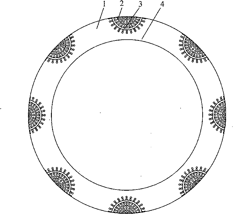
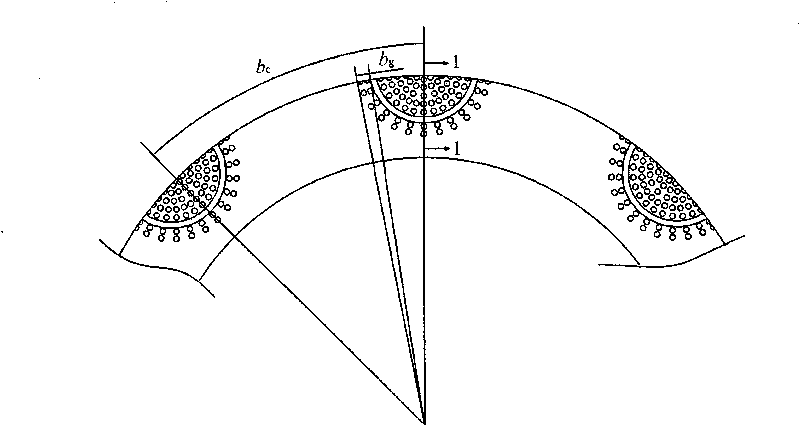
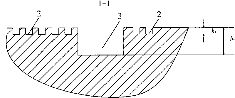
[0026] refer to Figure 1-3 , a liquid lubricated end face seal structure with cross-scale surface texture features, including a dynamic ring and a static ring of a mechanical seal, one side of the end faces of the dynamic ring and the static ring is the high pressure side, that is, the upstream, the dynamic ring and the static ring The other side of the end face of the static ring is the low-pressure side, that is, the downstream side. Several cross-scale textured face grooves are processed on the end face of the moving ring or the static ring of the mechanical seal. The cross-scale textured face grooves are composed of mm-level The deep groove 3 is composed of micron-scale micropores 2, the deep groove 3 is located upstream of the end face, and the micropores 2 are distributed around the deep groove 3; a sealing weir 1 is provided between the cross-scale textured surface grooves, An annular sealing dam 4 of an unopened face groove is arranged downstream of the cross-scale te...

Embodiment 2

[0033] refer to Figure 4 , Figure 5 The difference between this embodiment and the first embodiment is that the deep groove 3 is semicircular, and the bottom surface of the deep groove 3 is processed with microholes 2 . The rest of the structure and implementation are the same as in Embodiment 1. The shape of the deep groove 3 can also be rectangle 31, E shape 32, crescent shape 33, X shape 34, T shape 35, U shape 36, V shape 37, other shapes such as trapezoid 38, refer to Figure 7 .

Embodiment 3

[0035] refer to Figure 4 , Figure 6 The difference between the present embodiment and the second embodiment is that the depth of the microholes 2 on the bottom surface of the deep groove 3 gradually becomes shallower along the radial direction from upstream to downstream, which enhances the pumping effect. The rest of the structures and implementations are the same as in Embodiment 2.


PUM


Abstract

The invention discloses a liquid lubricated end face seal structure with a cross-scale surface texture characteristic, which comprises a moving ring and a static ring of a mechanical seal; and one side of an end face of the moving ring/static ring is a high pressure side, namely an upstream, while the other side is a low pressure side, namely a downstream. The liquid lubricated end face seal structure is characterized in that: a plurality of cross-scale texture face grooves are processed on the end face of the moving ring or the static ring of the mechanical seal; each cross-scale texture face groove consists of a millimeter deep groove and micrometer micropores; the deep groove is positioned at the upstream of the end face; the micropores are distributed on the periphery of the deep groove; seal weirs are arranged between the cross-scale texture face grooves; and a downstream of each cross-scale texture face groove is provided with an annular seal dam of a non-opened face groove. The liquid lubricated end face seal structure has the advantages of improving seal lubrication, improving the rigidity of a fluid film and the pressure and heat resistance of the mechanical seal, greatly strengthening the operational reliability, stability and leak tightness of the seal, and prolonging the service life of the seal.

Description

technical field [0001] The invention relates to a mechanical end face sealing structure for liquid medium, in particular to a liquid end face sealing structure with cross-scale surface texture characteristics composed of millimeter-scale microgrooves and micron-scale micropores, especially suitable for high pressure, high temperature and high speed Pump shaft end seal occasions. Background technique [0002] From the 1970s to the 1990s, breakthroughs have been made in mechanical end face seal technology, especially high-parameter pump end face seal technology, such as dry gas end face seals for high-speed applications, thermal fluid power wedge mechanical end face seals for high-pressure or high-temperature applications, etc. It has been successfully applied in the fields of petroleum, petrochemical, chemical industry, nuclear power and aerospace, but the known high-parameter mechanical end face seal for the pump shaft end still has some shortcomings. For example, ① the dry...

Claims


Application Information

Patent Timeline
IPC IPC(8): F16J15/16F04D29/12
Inventor 彭旭东卢碎榜李纪云孟祥铠
Owner ZHEJIANG UNIV OF TECH
Why Eureka
Try Eureka