
Sealing ring

A sealing ring and sealing lip technology, applied in the direction of engine seals, engine components, mechanical equipment, etc., can solve problems such as oil leakage, and achieve the effect of enhancing pump return and reducing fluid leakage

Pending Publication Date: 2021-10-12
SCHAEFFLER TECH AG & CO KG
View PDF2 Cites 0 Cited by
  • Summary
  • Abstract
  • Description
  • Claims
  • Application Information

AI Technical Summary

Problems solved by technology

Another part of the rib in this case will cause oil leakage

Method used


Image

  • Sealing ring
  • Sealing ring
  • Sealing ring

Examples


Embodiment Construction

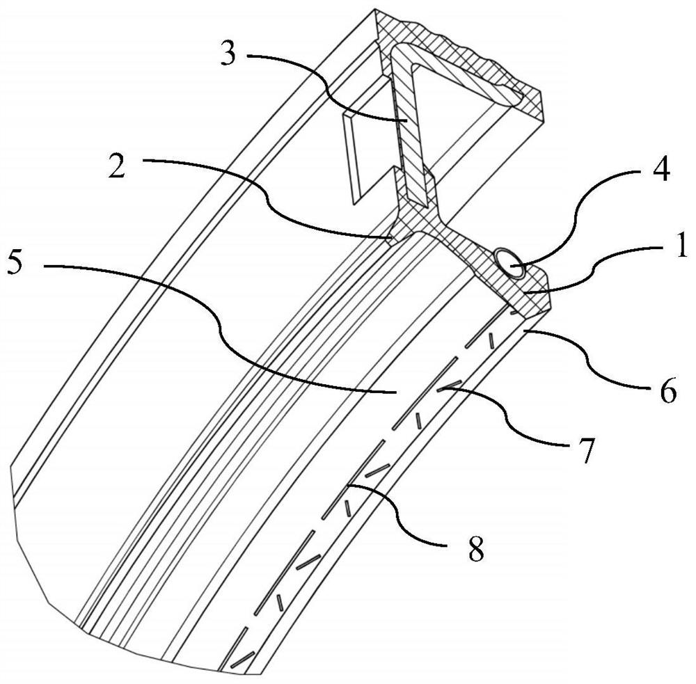
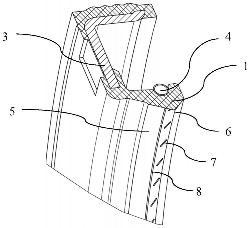
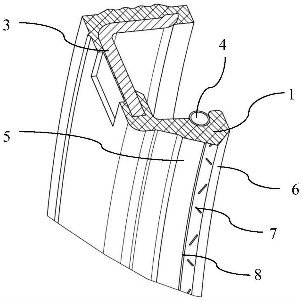
[0027] figure 1 is a partial perspective view of the sealing ring according to the first preferred embodiment. The sealing ring can be used for dynamic sealing of rotating shafts with bi-directional rotating conditions. especially if figure 1 As shown in the cross-section of the sealing ring in , the sealing ring includes an elastic sealing body made of elastomer, especially rubber, a skeleton 3 and a spring ring 4, wherein the elastic sealing body is at least partially covered here to support the sealing ring The skeleton 3.

[0028] The sealing ring according to the first embodiment forms by means of its elastic seal two sealing lips, namely a main lip 1 arranged on the fluid side and a dust lip 2 arranged on the air side. In this embodiment, the main lip 1 may abut against a rotating component (not shown) substantially radially, and the sealing portion formed by the main lip 1 and the rotating component may be formed on the outer peripheral surface of the rotating compon...


PUM


Abstract

The invention relates to a sealing ring. The sealing ring is provided with a sealing lip (1) made of an elastomer on the radial inner side of the sealing ring, and the sealing lip (1) is used for slidably abutting against a rotating component, so that dynamic sealing is formed between the air side and the fluid side; the sealing lip (1) comprises a first sealing inclined plane (5) facing the air side and a second sealing inclined plane (6) facing the fluid side, the included angle between the first sealing inclined plane (5) and the rotating component is smaller than that between the second sealing inclined plane (6) and the rotating component, and first ribs (7) close to the fluid side and second ribs (8) close to the air side are arranged on the first sealing inclined plane (5); and the first ribs (7) are configured as ribs which are distributed in the circumferential direction and extend substantially obliquely to the axial direction, and the second ribs (8) are configured as ribs which extend in the circumferential direction.

Description

technical field [0001] The present invention relates to sealing technology. The invention particularly relates to a sealing ring, especially a dynamic sealing ring. Background technique [0002] Lip seals for rotating shafts have been widely used in the sealing of rotating parts of various mechanical equipment. In order to improve the sealing performance of the sealing ring, in addition to adopting suitable materials and precise dimensions, an oil return structure according to fluid dynamics can also be arranged on the sealing part. For example, rib-shaped oil return lines of various structures can be formed on the sealing part, especially on the air side of the lip, through various groove structures opened on the mold. Especially under the condition of high-speed rotation, these oil return lines enhance the "pumping effect", which is beneficial for the fluid leaked from the fluid side of the sealing part to the air side to return to the fluid side to ensure the sealing ef...

Claims


Application Information

Patent Timeline
Patent Type & Authority Applications(China)
IPC IPC(8): F16J15/3244F16J15/3236F16J15/3208F16J15/324
CPCF16J15/3244F16J15/3236F16J15/3208F16J15/324
Inventor 刘鑫李定寇育豪
Owner SCHAEFFLER TECH AG & CO KG
Learn More