Supercharge Your Innovation With Domain-Expert AI Agents!

analog switch

A technology of analog switch and analog screen, which is applied in the direction of electrical components, supervision desk/panel, etc., to achieve the effect of simple mechanism and convenient production

Inactive Publication Date: 2012-02-22
王宁生
View PDF1 Cites 0 Cited by
  • Summary
  • Abstract
  • Description
  • Claims
  • Application Information

AI Technical Summary

Problems solved by technology

[0002]In the analog switch in the prior art, the knob rotating shaft mechanism is located under the bottom plate of the analog switch, which requires that a deep hole must be provided on the analog screen to be installed , as a result, the thickness of the simulation screen increases and the weight increases
Moreover, the analog switch has many parts, high cost, and complicated production and installation.

Method used


Image

  • analog switch
  • analog switch
  • analog switch

Examples


Embodiment 1

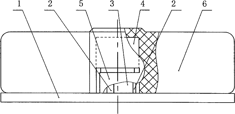
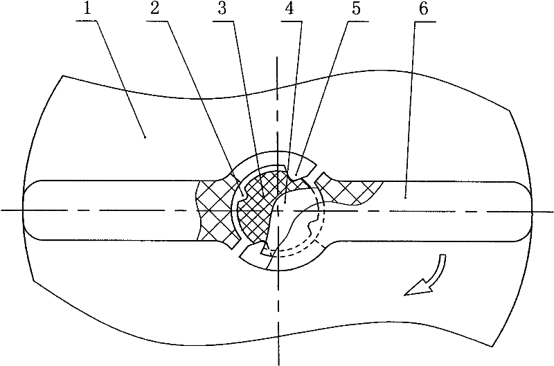
[0016] Embodiment one: figure 1 , figure 2 As shown, one side of the base plate 1 is provided with glue that is connected to the surface of the analog screen, and the other side of the base plate 1 is connected with one end of a small-diameter shaft 3 with a step shaft, and two to ten ends are arranged on the outer wall of the small-diameter shaft 3. There are two positioning slots 2 , and one to three elastic buckles 5 that can be snapped into the positioning slots 2 are provided on the hole wall of the button handle 6 .

Embodiment 2

[0017] Embodiment two: image 3 , Figure 4 As shown, the inner wall of the end of the step hole of the button handle 6 is provided with two to twelve grooves 7 . One side of the bottom plate 1 is provided with glue that connects with the surface of the analog screen, and the other side of the bottom plate 1 is connected with one end of a small-diameter shaft 3 of a stepped shaft, and the outer wall of the large-diameter shaft 4 of the stepped shaft is provided with one to four clips. The protruding teeth 11 that enter the groove 7, and the periphery of each protruding tooth 11 is provided with an elastic escape slit 10. Between small-diameter shaft 3 and button handle 6 holes, be provided with the cover 9 that closely matches with button handle 6.

Embodiment 3

[0018] Embodiment three: Figure 5 , Figure 6 , Figure 7 As shown, one side of the bottom plate 1 is provided with glue connected to the surface of the analog screen, and the other side of the bottom plate 1 is connected with a small-diameter shaft 3 with a stepped shaft. The outer wall of the small-diameter shaft 3 is provided with four to eight opposite sides. parallel planes. Open seams 12 are provided on both sides of the button handle 6 holes, and spring buckles 8 are arranged in the seams 12, and the spring buckles are stuck on one group of opposite side surfaces in four to eight opposite side parallel surfaces. The spring buckle is formed by bending the elastic material into a semicircle, and the two ends are bent inward and parallel.


PUM


Abstract

The invention discloses an analog switch, and aims to provide an analog switch with simple structure and low cost. An analog switch that can be pasted freely on the analog screen. The feature is that one side of the bottom plate is provided with glue connected with the surface of the analog screen, and one end of a small-diameter shaft of a stepped shaft is connected on the other side of the bottom plate, and a hole is provided on the button handle, and the hole is sleeved on the stepped shaft. The outer wall of the small-diameter shaft is provided with two to twelve positioning grooves, and the hole wall of the button handle is provided with one to twelve elastic buckles each of which can be snapped into the positioning grooves. Two to twelve grooves are arranged on the inner wall at the inner end of the step hole of the button handle. The outer wall of the large-diameter shaft of the stepped shaft is provided with one to twelve protruding teeth, each of which can be snapped into a groove, and each protruding tooth is provided with an elastic relief seam around its periphery. Between the small-diameter shaft of the step shaft and the button handle hole, there is a sleeve tightly matched with the button handle. Four to eight parallel opposite sides are arranged on the outer wall of the small-diameter shaft. Open seams are provided on both sides of the button handle hole. The seam is provided with a spring buckle stuck on the parallel surface opposite the side of the small-diameter shaft.

Description

technical field [0001] The invention relates to a switch on an analog line screen. In particular, it is an analog switch that can be arbitrarily pasted on the analog screen. Background technique [0002] In the analog switch in the prior art, the button-moving shaft mechanism is arranged under the bottom plate of the analog switch, which requires a deep hole to be installed on the analog screen, thus causing the thickness of the analog screen to increase and the weight to increase. Moreover, the analog switch has many parts, high cost, and complicated production and installation. Such as Chinese Patent Publication No. CN2062120, date of disclosure on September 12, 1990, utility model name: analog switch knife switch, application number 89219379.4. Contents of the invention [0003] The invention overcomes the defects in the prior art, and proposes an analog switch that can be arbitrarily pasted on the analog screen, and its position can be changed at will. [0004] T...

Claims


Application Information

Patent Timeline
Patent Type & Authority Patents(China)
IPC IPC(8): H02B15/00
Inventor 王宁生王宗孚
Owner 王宁生
Features
  • R&D
  • Intellectual Property
  • Life Sciences
  • Materials
  • Tech Scout
  • Unparalleled Data Quality
  • Higher Quality Content
  • 60% Fewer Hallucinations
Learn More