
Lathe turnover fixture

A technology of flipping fixtures and lathes, which is applied in the direction of clamping, manufacturing tools, supports, etc., can solve the problems of easy pinch damage, difficult process balance, and low processing efficiency, so as to avoid pinch damage, achieve balance, and improve work efficiency. efficiency effect

Active Publication Date: 2010-05-05
江苏智慧工场技术研究院有限公司
View PDF1 Cites 13 Cited by
  • Summary
  • Abstract
  • Description
  • Claims
  • Application Information

AI Technical Summary

Problems solved by technology

[0002] Lathe processing products are usually processed on one side and clamped again to process the other side, or products with a certain angle are positioned and clamped by tooling according to the angle, and the angle turning is realized through the fixture, and the processing is carried out in sequence, usually in multiple installments Clamp processing to complete a part, often in mass production, a product needs to be realized on several lathes, that is, each lathe processes a process, so due to the size of the processing surface, the degree of difficulty is different, and the processing time of each process is different. In the case where the process is not easy to achieve balance, either use re-products for balance, or sacrifice equipment utilization. For small batch products, one side is usually processed first, and then the other side is processed. The processing efficiency is relatively low, and each side must be clamped once. Moreover, the principle that the rough datum can only be used once, so the workpiece after the second clamping is the fine datum after processing, which is prone to pinch defects. For the current competitive environment of multi-variety and small-batch production, many companies are increasingly Focusing on the concentration of processes, the application of functional fixtures is becoming more and more urgent. In response to the above situation, the company has invested manpower and material resources in the research and development of turning fixtures for lathes.

Method used


Image

  • Lathe turnover fixture
  • Lathe turnover fixture
  • Lathe turnover fixture

Examples


Embodiment Construction

[0010] The present invention will be further described below in conjunction with specific drawings and embodiments.

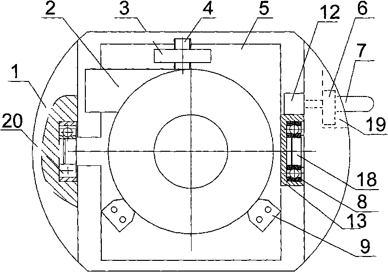
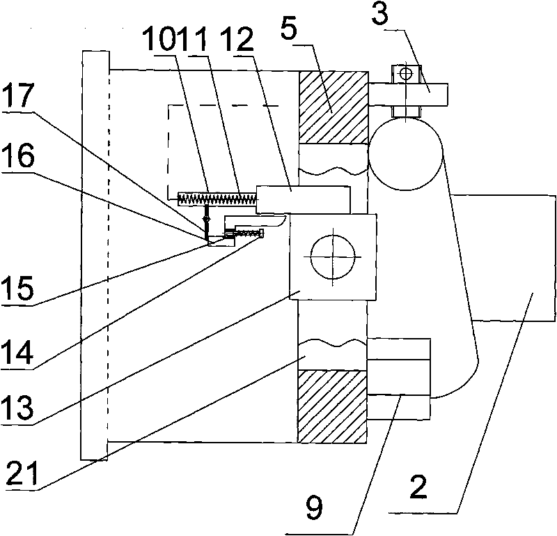
[0011] like figure 1 and 2 As shown: the present invention includes clamping body 1, workpiece 2, clamping seat 3, clamping screw rod 4, flip plate body 5, sliding key block 6, sliding handle 7, second bearing 8, positioning block 9, guide rail 10, Guide rail spring 11, rotary slide block 12, rectangular block 13, spring seat 14, push rod spring 15, push rod 16, rotating rod 17, rotating shaft 18, positioning groove 19, first bearing 20 and processing through hole 21 form.

[0012] One end of the clamp body 1 is provided with a first bearing 20, and the other end corresponding to the first bearing 20 is provided with a rotating shaft 18 on the clamp body 1, and one end of the flip plate body 5 is provided with a shaft, and the other end is provided with a shaft. One end is provided with a rectangular block 13, and the second bearing 8 is arranged in the descr...


PUM


Abstract

The invention relates to a fixture, particularly to a lathe turnover fixture. According to the technical scheme provided by the invention, the lathe turnover fixture comprises a fixture body; a first bearing is arranged at one end of the fixture body, a rectangular block is arranged at the other end of the fixture body, a second bearing is positioned in the rectangular block, a turnover plate body is arranged between the first bearing and the second bearing, a positioning block is arranged at one end of the turnover plate body, a workpiece clamping seat is arranged at the other end of the turnover plate body, and a clamping guide screw is arranged on the workpiece clamping seat; and a positioning groove is arranged on the fixture body, a sliding key block is arranged in the positioning groove, a sliding handle is arranged on the sliding key block, the sliding handle penetrates through the sliding key block and is fixedly connected with a rotating sliding block, the rotating sliding block and the rotating sliding block are in sliding contact, a guide rail is arranged at one end of the rotating sliding block, a rotating rod is arranged on the guide rail, a push rod is arranged between the rotating rod and the rectangular block, a push rod spring is arranged on the push rod, a spring seat is arranged at the end part of the push rod spring, and the spring seat is fixedly connected with the fixture body. The lathe turnover fixture has simple structure, convenient operation, capability of processing both surfaces of workpieces and high processing efficiency.

Description

technical field [0001] The invention relates to a fixture, in particular to a turning fixture for a lathe. Background technique [0002] Lathe processing products are usually processed on one side and clamped again to process the other side, or products with a certain angle are positioned and clamped by tooling according to the angle, and the angle turning is realized through the fixture, and the processing is carried out in sequence, usually in multiple installments Clamp processing to complete a part, often in mass production, a product needs to be realized on several lathes, that is, each lathe processes a process, so due to the size of the processing surface, the degree of difficulty is different, and the processing time of each process is different. In the case where the process is not easy to achieve balance, either use re-products for balance, or sacrifice equipment utilization. For small batch products, one side is usually processed first, and then the other side is ...

Claims


Application Information

Patent Timeline
Patent Type & Authority Applications(China)
IPC IPC(8): B23Q3/12
Inventor 孔宪刚陈飞李春建
Owner 江苏智慧工场技术研究院有限公司
Learn More