

Direct contact type cell co-culture device
A contact and co-cultivation technology, applied in tissue cell/virus culture devices, biochemical equipment and methods, biochemical instruments, etc., can solve the problems of inability to achieve direct contact co-culture of cells, and achieve reliable results and simple operation Effect
- Summary
- Abstract
- Description
- Claims
- Application Information
AI Technical Summary
Problems solved by technology
Method used
Image

Examples
Embodiment 1
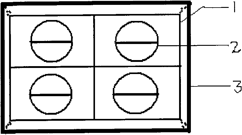
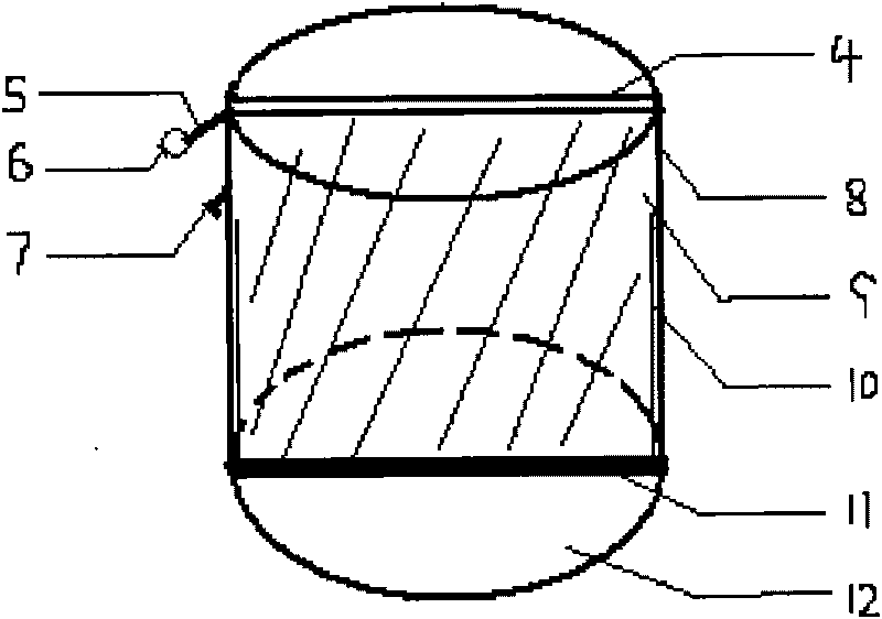
[0021] A direct contact cell co-culture device, such as figure 1 and figure 2 As shown, it consists of a culture well 2, a culture plate 1 and an upper cover 3. The culture hole 2 is set on the culture plate 1, and the upper cover 3 covers the culture plate 1 and closes the culture hole 2; the culture hole 2 is provided with an isolation plate 9. Divide the culture well 2 into two culture chambers, which can realize the co-cultivation of two different adherent cells.
[0022] There are 1-48 culture holes 2, and barbs 7 are arranged on the outer wall of the upper part of the culture holes 2.
[0023] One isolation plate 9 is provided for 2 in the cultivation hole.
[0024] The two vertical sides of described separating plate 9 are installed in the side fixing groove 10 that is provided with in the culture hole, and the bottom edge of separating plate 9 is pressed on the elastic pad 11 of culture hole bottom 12, and the top of separating plate 9 is installed on In the upper ...
Embodiment 2
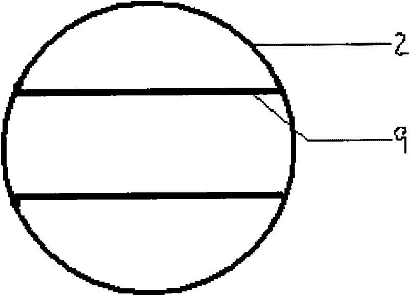
[0027] A direct contact cell co-cultivation device, the structure is the same as that of Example 1, the difference is that two parallel isolation plates 9 are arranged in the culture hole 2, and the culture hole 2 is divided into 3 culture chambers, which can realize three culture chambers. Co-cultivation of different adherent cells, such as image 3 shown.
Embodiment 3
[0029] A direct contact cell co-cultivation device, the structure is the same as that of Example 1, the difference is that three parallel isolation plates 9 are arranged in the culture hole 2, and the culture hole 2 is divided into 4 culture chambers, which can realize four culture chambers. Co-cultivation of different adherent cells, such as Figure 4 shown.
PUM
 Abstract
Description
Claims
Application Information