Mechanical continuous variable valve lift mechanism

A valve lift, mechanical technology, applied in the direction of mechanical equipment, machine/engine, engine components, etc., can solve the problems of difficult control, complex mechanism, not multi-level intelligent control, etc., and achieve the effect of small work wear

Inactive Publication Date: 2010-05-05
丛培伟
View PDF6 Cites 13 Cited by
  • Summary
  • Abstract
  • Description
  • Claims
  • Application Information

AI Technical Summary

Problems solved by technology

[0005] First, the mechanism structure is complicated, the cost is expensive, and the installation is difficult, so it cannot be popularized and promoted
[0006] At present, the existing continuously variable valve lift technology in the world (including unrealized patents) is not only complex in mechanism but also has a large number of components, and requires a large space volume when installed, so it can only be installed in larger valves with medium displacement and above. On the engine, and also increase the volume of the engine cylinder head
Due to the difficulty of installation and high cost, it cannot be extended to small displacement engines
[0007] Second, the problem of the design mechanism of the double cam method
The valve timing changed in this way should be adjusted by the valve timing controller; however, the actual control of the valve timing controller in the world is still a combined switching mode based on two-level control, not multi-level intelligent control.
In some patents, the valve timing can be changed to a maximum crankshaft angle of 80 degrees, which is an angle that is difficult for the valve timing controller to achieve
In addition, when the valve timing controller rotates the camshaft, a large actuation force is required, so it is difficult for the valve timing controller to switch synchronously with the engine throttle in real time.
[0010] Third, the control accuracy of the valve lift
[0011] The reason why the control accuracy of the current continuously variable valve lift technology is insufficient or difficult to control is because the working end surface of the variable rocker arm (or swing rod, second cam) is a cam shape with large fluctuations, that is, the basis can be The variable mechanism is the double cam method
The specific manifestation is that it is very difficult to slightly change the low valve lift, and the valve opening time is extremely small at the same time when the valve lift is small, so the practical significance of setting a small valve lift becomes difficult to understand; the valve opening speed changes at medium speeds The rapidity is not smooth; when switching at high speed, the control values ​​are intensive, and the valve lift changes greatly when the control distance (or control angle) is very small, which is not easy to control
[0012] Fourth, the problem of controlling the actuation force and maintaining force
This brings great difficulties to control the actuation force when switching and control the maintenance force after switching (to maintain it without shaking)

Method used


Image

  • Mechanical continuous variable valve lift mechanism
  • Mechanical continuous variable valve lift mechanism
  • Mechanical continuous variable valve lift mechanism

Examples


Embodiment 1

[0105] In order to avoid possible explanation confusion, unless otherwise specified, the following valves all refer to the valve corresponding to the variable rocker arm (301), that is, the valve (100). The reasons for the mutual occlusion or marking difficulty between components, if a certain schematic diagram cannot mark a certain component, you can refer to other schematic diagrams.

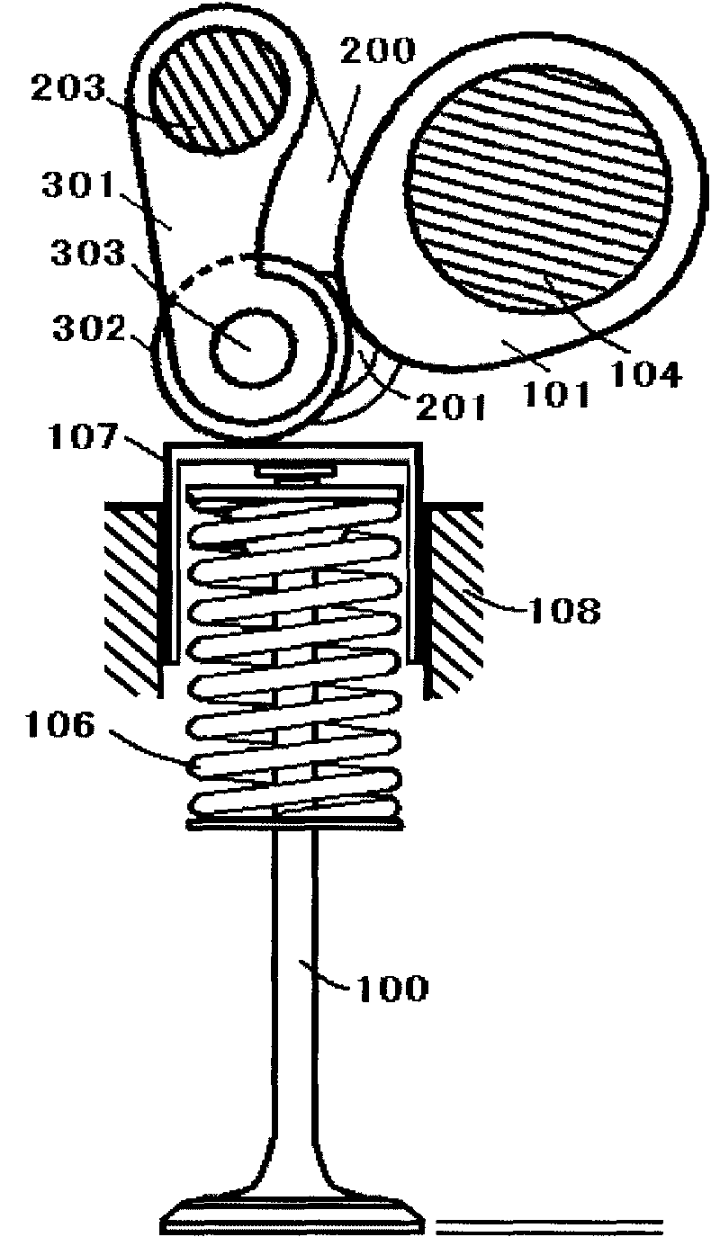
[0106] figure 1 Shown is a schematic structural diagram of a continuously variable valve lift mechanism in the case of a valve lifter (for ease of expression, the valve lifter (107) is represented by a mechanical valve lifter), mainly including the cam (101), crank arm (200), crank arm journal (201), variable rocker shaft (203), variable rocker arm (301), valve tappet (107), tappet seat (108), auxiliary return spring (403) , Valve (100). The crank arm (200) and the crank arm journal (201) are fixedly connected (also can be processed in one piece); the crank arm journal (201) is installed to ...

Embodiment 2

[0112] 1. Engines above medium displacement

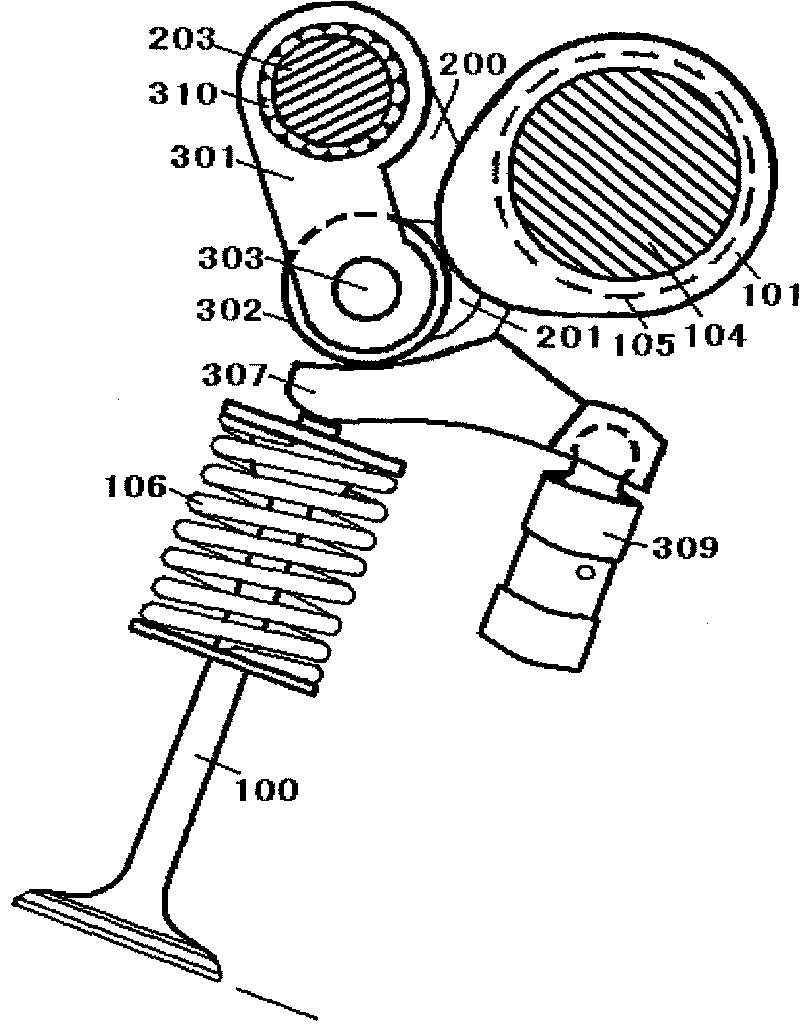
[0113] figure 2 Shown is a schematic structural diagram of a continuously variable valve lift mechanism in the case of a sliding rocker arm, which mainly includes a cam (101), a crank arm (200), a crank arm journal (201), a variable rocker shaft (203), Variable rocker arm (301), sliding surface rocker arm (307), valve clearance automatic compensator (309), auxiliary return spring (403), valve (100) and dotted lines show the camshaft journal (105); where The working state and setting of crank arm (200), crank arm journal (201), variable rocker arm (301), auxiliary return spring (403) and embodiment 1 are exactly the same. The needle roller bearing arranged in the middle on the variable rocker arm (301) is in close contact with the cam (101), and the two needle roller bearings on both sides conflict with the working end faces of the corresponding sliding surface rocker arm (307) respectively. One end of the sliding surface rocker ...


PUM


Abstract

The invention relates to a mechanical continuous variable valve lift mechanism which can lead the lift capacity of an engine valve to be changed into being closed all the way from the maximum according to the preset control value and ensure the valve timing not to be changed. The mechanism comprises a cam (101), an actuating mechanism (20) of a changeable rocker arm, the changeable rocker arm (301), a valve tappet (107), a tappet seat (108), a valve (100) and an auxiliary return spring (403); wherein the actuating mechanism (20) of the changeable rocker arm is provided with a changeable rocker arm shaft (203) which is connected with the changeable rocker arm (301), can control and change the space mechanical characteristics of the changeable rocker arm (301) and used for leading the lift capacity of the valve (100) to be continuously changed. The invention aims at thoroughly solving the problem of variable gas distribution of an internal-combustion engine puzzling the engine industry for dozens of years, omits a throttle valve of the engine, and leads continuous variable valve lift technology to be popularized to a minitype engine with less emission.

Description

technical field [0001] The invention relates to a mechanical continuously variable valve lift mechanism, which can make the valve lift of the engine vary from maximum to closed according to a preset control value and keep the valve timing constant. Background technique [0002] As we all know, because of the requirements of the best air-fuel ratio of the engine, the air volume of the cylinder must be precisely controlled for different working conditions, that is, how much air should be taken in with the throttle, otherwise the combustion will be insufficient and emission problems will occur. Technologies that can precisely control the air distribution of the engine include throttle technology and continuously variable valve lift technology. At present, the engine uses the throttle technology to control the intake air volume of the cylinder, but the throttle technology is not the technology that best meets the engine gas distribution requirements. For the throttle condition,...

Claims


Application Information

Patent Timeline
Patent Type & Authority Applications(China)
IPC IPC(8): F01L13/00F01L1/344F01L1/18F01L1/053
Inventor 丛培伟
Owner 丛培伟
Why Eureka
Try Eureka