Manufacturing method of plug-in terminal of connector

A manufacturing method and connector technology, applied in the field of electronics, can solve the problems of difficult to guarantee coplanarity, many processes, easy bending and deformation, etc., and achieve the effects of improving production efficiency, reducing manufacturing cost, and improving position accuracy

Active Publication Date: 2010-05-05
SHENZHEN JIANDUAN TECH
View PDF0 Cites 3 Cited by
  • Summary
  • Abstract
  • Description
  • Claims
  • Application Information

AI Technical Summary

Problems solved by technology

For the situation before the two rows of conductive terminals are respectively inserted into the insulating plastic body, refer to figure 1 and figure 2 , since each conductive terminal is in the shape of a thin strip, it is easy to bend and deform, so it is difficult to guarantee the coplanarity of the first row of conductive terminals 1 and the second row of conductive terminals 2 in the manufacturing process of the female base product. It is also very difficult to achieve high position accuracy for

Method used


Image

  • Manufacturing method of plug-in terminal of connector
  • Manufacturing method of plug-in terminal of connector
  • Manufacturing method of plug-in terminal of connector

Examples


Embodiment Construction

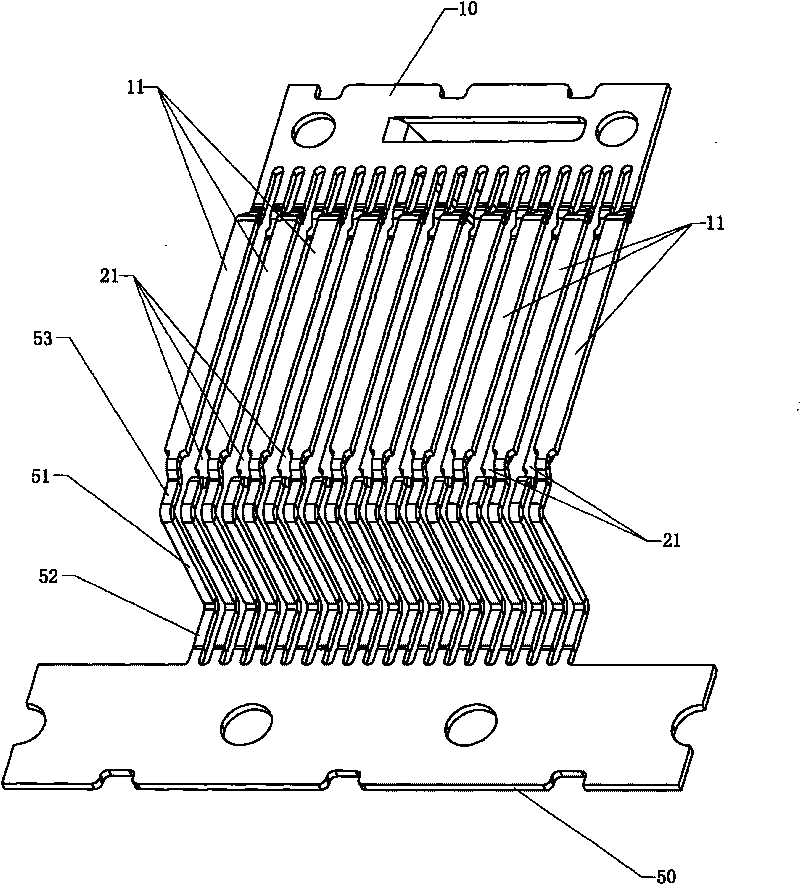
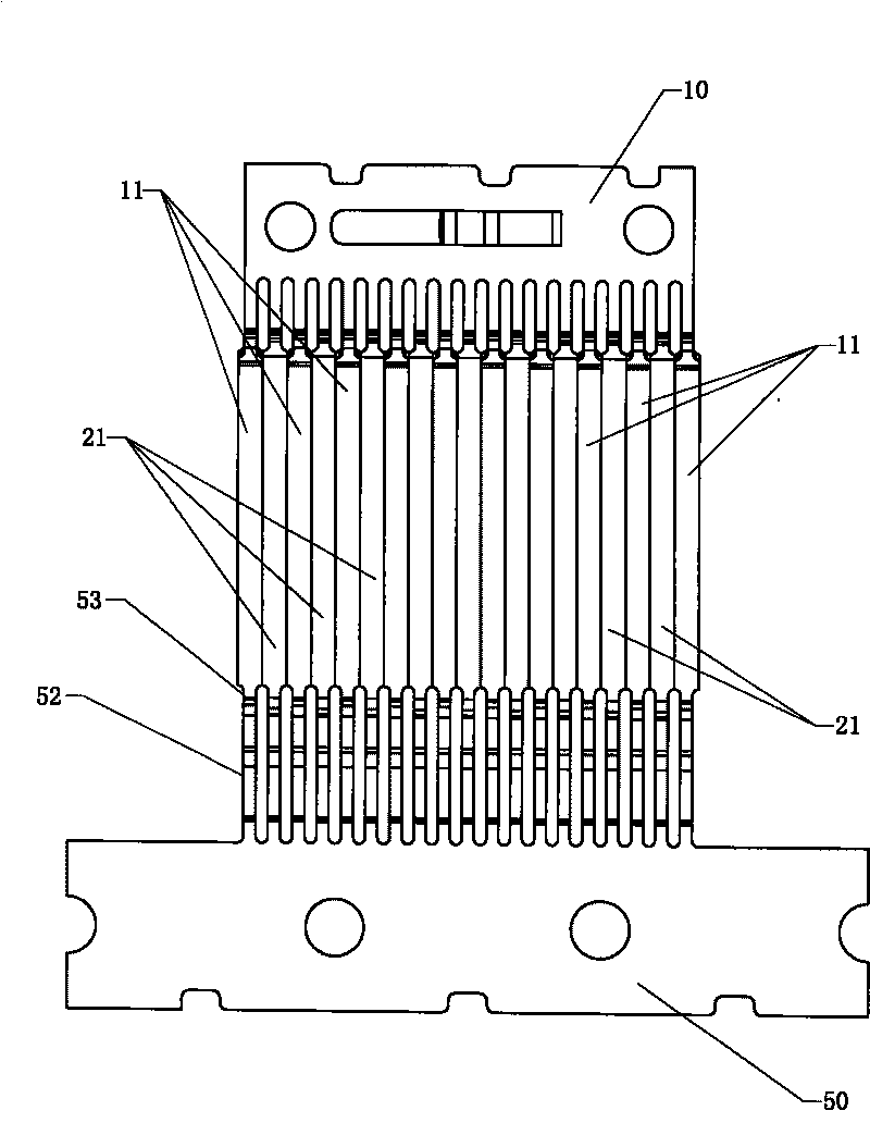
[0035] Figure 1-Figure 10 A specific embodiment of the invention is shown.

[0036] In this embodiment, the manufacturing method of the plug-in terminal of the connector includes the following steps:

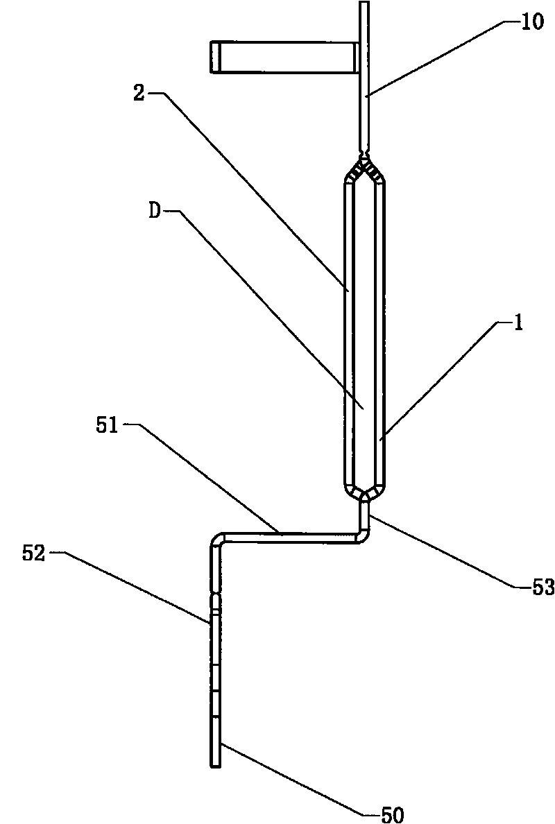
[0037]a. Form the first row of conductive terminals 1 (including several conductive terminals 11) and the second row of conductive terminals 2 (including several conductive terminals 21) of connector insertion terminals on the metal strip, the first row of conductive terminals 1 and the second row of conductive terminals One end of the row of conductive terminals 2 is connected through the front connecting strip 10, and the other end is connected through the rear connecting strip 50;

[0038] At the front end, along the thickness direction of the metal strip (see image 3 , image 3 The horizontal direction in is the thickness direction of the metal strip, that is, the thickness direction of the first row of conductive terminals 1 and the second row of conductive terminals 2...


PUM


Abstract

The invention provides a manufacturing method of a plug-in terminal of a connector, a first model and a second model are adopted, equal-height heaves are arranged on both opposite surfaces of the first model and the second model, the tail ends of all heaves of the first model are coplanar, and the tail ends of all heaves of the second model are coplanar; the first model and the second model are moved to the first row of conducting terminals and the second row of conducting terminals from two opposite directions, and the heaves of the first model are inserted between two adjacent conducting terminals of either of the first row of conducting terminals and the second row conducting terminals, and the heaves of the second model are inserted between two adjacent conducting terminals of the other one of the first row conducting terminals and the second row of conducting terminals; and a space formed between the first row of conducting terminals and the second row of conducting terminals is filled with insulating materials. The invention can effectively improve the position precision of the conducting terminals in the manufacturing process and the respective coplanarity both of the first row of conducting terminals and the second row of conducting terminals and correspondingly improve the quality of the connector and the plugged-in terminal. The method is simple in steps and easy to implement, and can improve the production efficiency and reduce the manufacturing cost by improving the product quality.

Description

【Technical field】 [0001] The invention relates to electronic technology, in particular to a method for manufacturing an insertion terminal of a connector which can improve the position accuracy of a conductive terminal. 【Background technique】 [0002] Existing HDMI female base products use two independent rows of conductive terminals to be inserted into the insulating plastic body respectively, and then use a jig to press them into the PIN slot in the insulating plastic body after inserting the insulating plastic body; finally, the terminal strip is broken off . In this way, on the one hand, the conductive terminals are insulated from each other; on the other hand, the conductive terminals and the insulating plastic are integrated to form the insertion terminal of the connector; at the same time, structural strength is provided to facilitate the insertion and removal of the connector plug. For the situation before the two rows of conductive terminals are respectively insert...

Claims


Application Information

Patent Timeline
IPC IPC(8): H01R43/16
Inventor 曾建智
Owner SHENZHEN JIANDUAN TECH
Why Eureka
Try Eureka