High-power density permanent magnetic brushless motor with moment holding function for mechanical arm

A permanent magnet brushless motor, high power density technology, applied in the direction of electromechanical devices, electrical components, magnetic circuit static parts, etc., can solve the problem of complex motor system structure, reduce complex procedures, achieve simple structure, large torque output effect

Active Publication Date: 2010-05-05
HARBIN INST OF TECH
View PDF0 Cites 7 Cited by
  • Summary
  • Abstract
  • Description
  • Claims
  • Application Information

AI Technical Summary

Problems solved by technology

[0003] The purpose of the present invention is to provide a high power density permanent magnet brushless motor for a manipulator with a torque holding function, which solves the problem that the existing space manipulator needs to be equipped with a gear reduction device for driving with a high-speed motor, which makes the structure of the motor system complex. question

Method used


Image

  • High-power density permanent magnetic brushless motor with moment holding function for mechanical arm
  • High-power density permanent magnetic brushless motor with moment holding function for mechanical arm
  • High-power density permanent magnetic brushless motor with moment holding function for mechanical arm

Examples


specific Embodiment approach 1

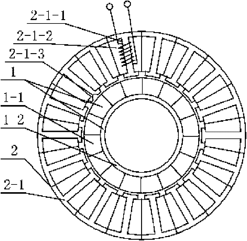
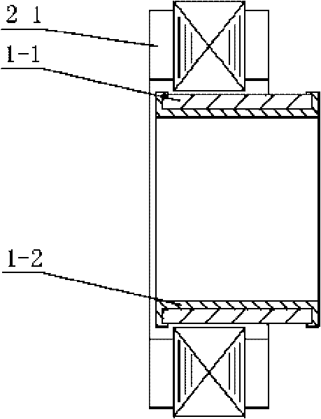
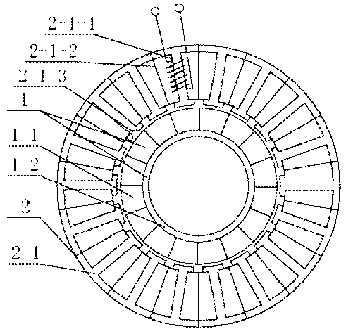
[0007] Specific implementation mode one: the following combination Figure 1-Figure 2 Describe this embodiment. This embodiment includes a hollow disk permanent magnet rotor 1 and a stator 2. The hollow disk permanent magnet rotor 1 is composed of a rotor pole 1-1 and a snap ring rotor yoke 1-2. The rotor pole 1-1 and The snap ring rotor yoke 1-2 adopts gap fit; the stator 2 is composed of multiple stator cores 2 1, each stator core 2-1 has a stator tooth, and the multiple stator cores 2-1 are connected end to end to form mutual intervals The stator teeth 2-1-1 and the stator slots 2-1-2, the stator teeth 2-1-1 are wound with three-phase symmetrical windings in the form of fractional slots, the number of turns of each phase winding is equal, and each stator tooth 2 - The same-phase windings wound on 1-1 are connected in series; there is an air gap between the inner circular surface of the multiple stator cores 2-1 and the outer circular surface of the rotor magnetic pole 1-1; ...

specific Embodiment approach 2

[0015] Embodiment 2: This embodiment differs from Embodiment 1 in that the radius range of the semicircular groove 2-1-3 is 0.1mm-0.2mm. Other components and connections are the same as those in Embodiment 1.

[0016] The radius of the semicircular groove 2-1-3 depends on the size of the required positioning and holding torque. If the positioning and holding torque is large, the radius should be relatively larger, and vice versa.

specific Embodiment approach 3

[0017] Embodiment 3: The difference between this embodiment and Embodiment 1 or 2 is that the range of the air gap is 0.25mm-0.35mm. Other compositions and connections are the same as those in the first or second embodiment.

[0018] The air gap can be reduced as much as possible under the premise of ensuring the assembly requirements, which can properly increase the air gap magnetic field density and improve the power density of the motor.


PUM


Abstract

The invention relates to a high-power density permanent magnetic brushless motor with moment holding function for a mechanical arm, belonging to the technical field of motors and solving the problem that a gear reducing device is required to be arranged in the traditional space mechanical arm driven by a high-speed motor to cause the motor system to have complex structure. A hollow disc type permanent magnetic rotor of the high-power density permanent magnetic brushless motor comprises a rotor magnetic pole and a clasp type rotor yoke, wherein the rotor magnetic pole and the clasp type rotor yoke are in clearance fit; each rotor iron core of a stator is provided with a stator tooth, a plurality of stator iron cores are connected in an end-to-end way to form the stator teeth and stator slots, which are arranged at intervals, three phases of symmetrical windings are arranged on the stator teeth in a fractional slot way, turn numbers of the each phase of windings are same, the same phase of windings wound on each stator tooth are mutually connected in series; air gaps are arranged between inner circle surfaces of the plurality of stator iron cores and outer circle surface of the rotor magnetic pole; and partial stator teeth in the stator teeth of the plurality of stator iron cores are provided with semicircular slots at the air gap sides to enable the motor body to have the moment holding function. The invention is used for the position control of the space mechanical arm.

Description

technical field [0001] The invention relates to a high power density permanent magnet brushless motor for a mechanical arm with torque holding function, and belongs to the technical field of motors. Background technique [0002] The motor systems used to drive high-precision robotic arms on the ground, aerospace robotic arms, and lunar rover robotic arms for lunar exploration projects all need to enable the robotic arm to overcome the gravitational force of the earth or the moon and maintain its position in the event of a power failure. state, will not slip. In order to reduce the volume of the mechanical arm in the special working environment of the moon or other space, the drive motor needs to be small in size, light in weight, high in efficiency and reliable in operation. Since the rotational speed required at the end of the manipulator is usually very low, in the prior art, in order to reduce the size of the manipulator, the motor system mostly uses a high-speed brushle...

Claims


Application Information

Patent Timeline
Patent Type & Authority Applications(China)
IPC IPC(8): H02K29/00H02K1/27H02K1/14H02K1/16
Inventor 尚静陆永平邹继斌刘承军徐永向胡建辉张诚诚
Owner HARBIN INST OF TECH
Why Eureka
Try Eureka