LED lamp bulb

A technology for LED bulbs and lampshades, which is applied to lampshades, cooling/heating devices of lighting devices, lighting and heating equipment, etc., can solve the problems of high production cost, shortened service life of LEDs, and heavy weight, and can solve the problem of heat dissipation and prolong the The effect of long service life and low production cost

Inactive Publication Date: 2010-05-12
东莞市贺喜光电有限公司
View PDF8 Cites 39 Cited by
  • Summary
  • Abstract
  • Description
  • Claims
  • Application Information

AI Technical Summary

Problems solved by technology

[0003] At present, commercially available LED light bulbs include a lamp holder, a lampshade, an aluminum substrate, and LEDs installed and fixed on the aluminum substrate. Electrically connected, the lampshade is installed and fixed on the top of the aluminum substrate to cover the LED. When the LED is working for lighting, the light generated by the LED can be irradiated through the lampshade to achieve the purpose of lighting. However, when the above-mentioned LED bulb is working, Since the LED will generate a lot of heat, only by dissipating the heat generated by the LED in a timely manner through the aluminum alloy heat sink at the bottom of the aluminum substrate can the normal operation of the LED be maintained, otherwise, the service life of the LED will be shortened, or even burn out, so , the existing LED light bulbs generally install and fix the LED on the aluminum substrate, and set the aluminum alloy heat sink. However, the weight of the aluminum substrate and the aluminum alloy heat sink is relatively large, and it takes up a certain volume of the LED bulb, making the existing LED Bulbs are heavy, bulky and expensive to produce
[0004] In addition, the LEDs in the LED bulb emit light concentratedly in one direction, causing the LED bulb to emit light unevenly, forming dark areas on both sides of the LED bulb, which is also a problem that cannot be solved by the LED bulbs in the prior art

Method used


Image

  • LED lamp bulb
  • LED lamp bulb
  • LED lamp bulb

Examples


Embodiment Construction

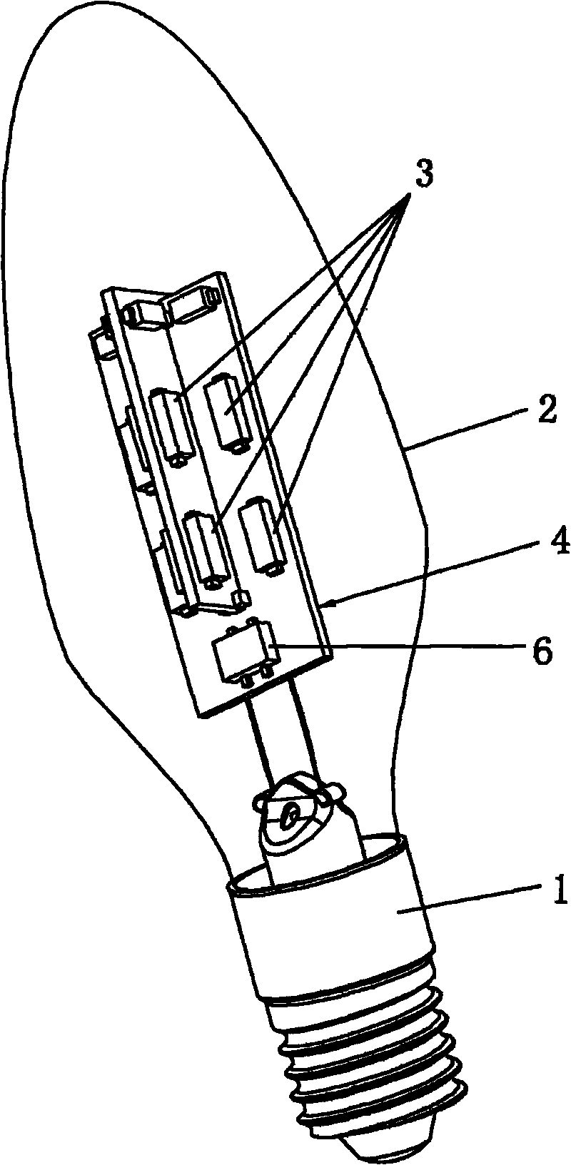
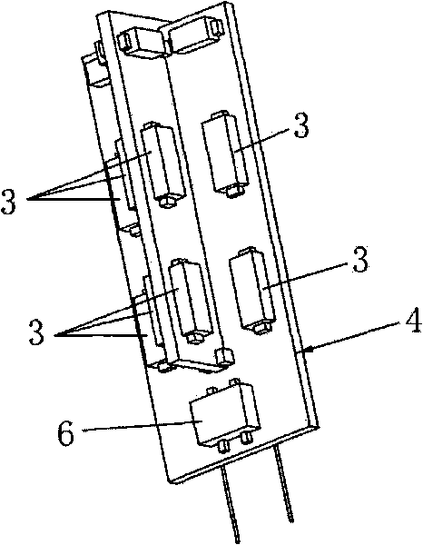
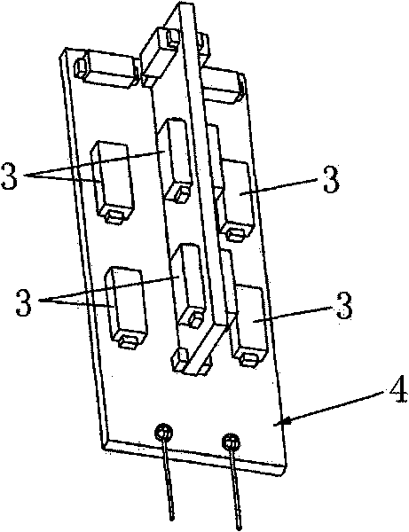
[0026] Below in conjunction with accompanying drawing, the present invention will be further described, please refer to Figures 1 to 4 The LED light bulb includes a lamp cap 1, a lampshade 2, an LED 3 and a circuit board 4. The bottom end of the lampshade 2 is installed and fixed on the top of the lamp cap 1, so that the lamp cap 1 can close the opening of the lampshade 2, and the circuit board 4 is installed and fixed on the lampshade 2. Inside, the circuit board 4 is electrically connected to the lamp holder 1 .

[0027] The lampshade 2 is filled with a mixed gas for conducting heat.

[0028] Further, the mixed gas is a mixed gas composed of nitrogen and argon, wherein nitrogen gas accounts for 30%-90% of the total volume of the mixed gas, and argon accounts for 10%-70% of the total volume of the mixed gas.

[0029] Because the lampshade of the present invention is filled with mixed gas, when the LED is working for lighting, the LED will generate heat, and the mixed gas in...


PUM


Abstract

The invention relates to the technical field of lighting lamps, in particular to an LED lamp bulb which comprises a lamp holder, a lamp shade, an LED and a circuit board, wherein the bottom end of the lamp shade is installed and fixed at the top end of the lamp holder; the circuit board is installed and fixed inside the lamp shade and electrically connected with the lamp holder; and the interior of the lamp shade is filled with mixed gas used for conducting heat generated by the LED to the exterior of the lamp bulb. As the heat generated by the LED is emitted by the mixed gas, the LED lamp bulb has the characteristics of light weight, small volume and low production cost; in addition, the mixed gas is used as the medium of heat transmission, therefore the LED lamp bulb can quickly emit the heat generated by the LED to the exterior of the lamp bulb, with fast heat dissipation speed, thus effectively resolving the heat dissipation problem of the LED and prolonging the service life of the LED.

Description

Technical field: [0001] The invention relates to the technical field of lighting fixtures, in particular to an LED light bulb. Background technique: [0002] In recent years, LEDs (Light Emitting Diodes, Light Emitting Diodes) have been widely used as light sources in daily life because of their long service life, low energy consumption, and remarkable energy saving. For example, some manufacturers have designed LED bulbs that can be directly installed in ordinary bulb sockets to replace existing bulbs such as tungsten lamps. [0003] At present, commercially available LED light bulbs include a lamp holder, a lampshade, an aluminum substrate, and LEDs installed and fixed on the aluminum substrate. Electrically connected, the lampshade is installed and fixed on the top of the aluminum substrate to cover the LED. When the LED is working for lighting, the light generated by the LED can be irradiated through the lampshade to achieve the purpose of lighting. However, when the ab...

Claims


Application Information

Patent Timeline
Patent Type & Authority Applications(China)
IPC IPC(8): F21S2/00F21V3/04F21V29/00F21V23/00F21Y101/02F21K9/232F21V29/60F21Y115/10
CPCF21K9/135F21V3/00F21Y2101/02F21Y2111/001F21K9/232F21Y2107/00F21Y2115/10
Inventor 林世凯向海鹏
Owner 东莞市贺喜光电有限公司
Why Eureka
Try Eureka