Transmission device of optical detector

A technology of optical detector and transmission device, which is applied in the direction of optical testing for flaws/defects, etc., which can solve problems such as error-prone, labor-intensive and time-consuming, and low efficiency, and achieve the effect of increasing stability

Inactive Publication Date: 2010-05-12
SUZHOU MINGFU AUTOMATIC SCI & TECH
View PDF0 Cites 3 Cited by
  • Summary
  • Abstract
  • Description
  • Claims
  • Application Information

AI Technical Summary

Problems solved by technology

The transmission device can effectively drive the PCB board and automatically clamp the PCB board after the transmission is in place, so as to solve the problem that the transmission device on the market must manually control the transportation of the PCB board and manually clamp the PCB board time-consuming, inefficient, and error-prone defects resulting from the process of

Method used


Image

  • Transmission device of optical detector
  • Transmission device of optical detector
  • Transmission device of optical detector

Examples


Embodiment Construction

[0011] The present invention will be described in detail below in conjunction with the accompanying drawings.

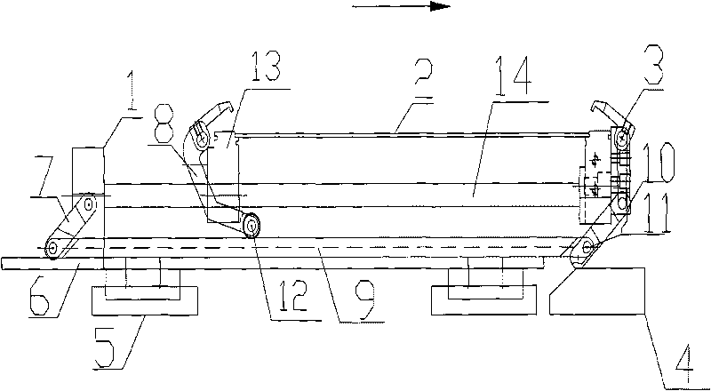
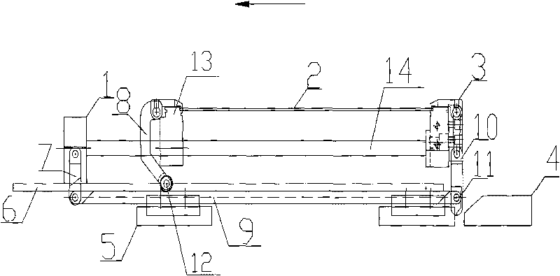
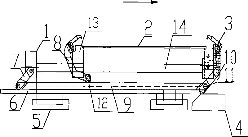
[0012] Such as figure 1 It is a schematic diagram of the movement of the transmission device of the optical detector of the present invention.

[0013] There are two slide rails (6) parallel to each other and perpendicular to the base (5) on the base (5), there is a blocking seat (4) at the end of the slide rail (6), and there is a connecting rod (14) on the slide rail (6). ) connected to the fixture tailstock (1) and the fixture table (13), the two ends of the fixture table (13) have symmetrically arranged pressure claws (3) and the steps for placing the PCB board (2), and the fixture tailstock (1) Connecting rod one (7) is connected through a rolling bearing, the end of the fixture table (13) away from the fixture tailstock (1) is connected with connecting rod four (10) through a rolling bearing, and connecting rod three (9) is connected to the connecting rod thro...


PUM


Abstract

The invention discloses a transmission device of an optical detector. Two sliding rails (6) which are mutually parallel and vertical to a base (5) are arranged on the base (5); the dead ends of the sliding rails (6) are provided with barrier seats (4); a clamp tailstock (1) and a clamp table (13) which are connected by a connecting rod (14) are arranged on each sliding rail (6); two ends of the clamp table (13) are provided with a pressure claw (3) and steps for placing a PCB (2), which are arranged symmetrically; a linkage I (7) is connected on the clamp tailstock (1) by a rolling bearing; one end of the clamp table (13), away from the clamp tailstock (1), is connected with a linkage IV (10) by a rolling bearing; a linkage III (9) is connected with the linkage I (7) and the linkage IV (10) by a rolling bearing (11); and the other end of the linkage IV (10) is connected with the pressure claw (3). The transmission device has the benefits of improving detection efficiency and accuracy, being capable of conducting transmission on the PCB and automatically clamping the PCB after transmission in place.

Description

technical field [0001] The invention relates to a transmission device, in particular to a transmission device used in an optical detector. Background technique [0002] The optical detector is a device that detects the solder joints of the PCB board after solder joint welding. The PCB board usually needs to detect the solder joints after welding, such as: detecting whether the solder joints are round and complete, or whether there is empty welding , Virtual welding, continuous welding and other phenomena. At present, the optical detectors on the market are usually operated manually. When a PCB board to be inspected is transported through the conveyor belt, the PCB board needs to be clamped and fixed manually through multiple fixing clips, and then through the camera or microscope. The lens is used to observe, and the welding condition of the solder joints on the PCB board can be obtained through visual or computer analysis. After the inspection is completed, the clamp is m...

Claims


Application Information

Patent Timeline
Patent Type & Authority Applications(China)
IPC IPC(8): G01N21/88
Inventor 庄春明
Owner SUZHOU MINGFU AUTOMATIC SCI & TECH
Why Eureka
Try Eureka