Soil water potential sensor

A soil water potential and sensor technology, applied in instruments, soil material testing, measuring devices, etc., can solve problems such as low response sensitivity, and achieve the effect of convenient exhaust and low exhaust frequency

Inactive Publication Date: 2010-05-12
HEILONGJIANG PROVINCIAL HYDRAULIC RES INST
View PDF0 Cites 12 Cited by
  • Summary
  • Abstract
  • Description
  • Claims
  • Application Information

AI Technical Summary

Problems solved by technology

[0004] The present invention aims to solve the problem of low response sensitivity of the existing soil water potentia

Method used


Image

  • Soil water potential sensor
  • Soil water potential sensor
  • Soil water potential sensor

Examples


specific Embodiment approach 1

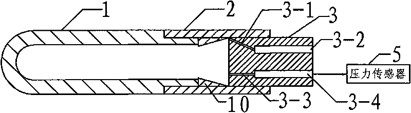
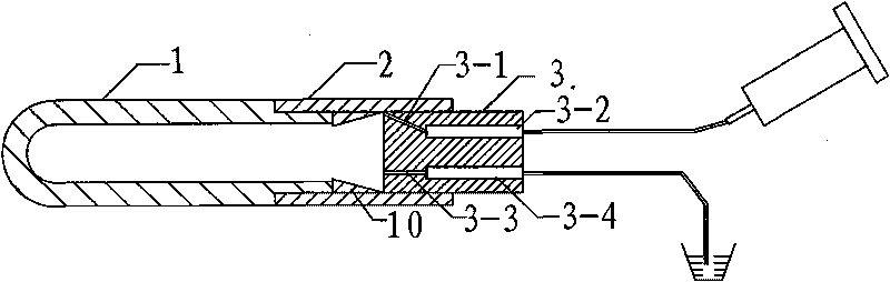
[0008] Specific implementation mode 1. Combination figure 1 Illustrate this specific embodiment, a soil water potential sensor, which includes a pressure sensor 5, and it also includes a clay head 1, an air collection chamber casing 2 and a pipe plug 3; the cross-sectional shape of the clay head 1 is U-shaped, and the clay head The inner cavity of 1 is a gas collection chamber, one end of the gas collection chamber casing 2 is sealed and fixed at the opening of the clay head 1, and the other end of the gas collection chamber casing 2 is sealed and fixed with a pipe plug 3, and the pipe plug 3 There is an air guide channel and a water inlet channel on the top, and the air guide channel and the water inlet channel are both connected to the gas collection chamber, and the pressure signal input end of the pressure sensor 5 is set at the water inlet hole of the water inlet channel of the pipe plug 3.

[0009] There are two main sources of air bubbles in the air collection chamber. ...

specific Embodiment approach 2

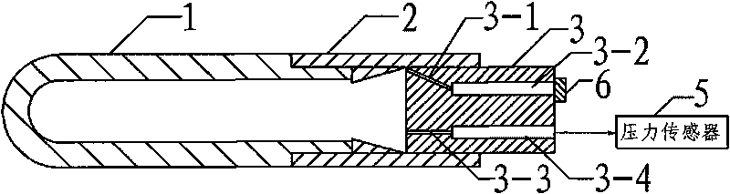
[0019] Embodiment 2. The difference between this embodiment and the soil water potential sensor described in Embodiment 1 is that the air guide channel is composed of a first air guide tube 3-1 and a second air guide tube 3-2. One end of the first air guide tube 3-1 communicates with the gas collection chamber, the other end of the first air guide tube 3-1 communicates with one end of the second air guide tube 3-2, and the other end of the second air guide tube 3-2 It is the air guide hole of the pipe plug 3 , and the port connecting the first air guide pipe 3 - 1 with the air collection chamber is located at the inner wall of the clay head 1 .

[0020] In this embodiment, a certain angle is set between the first air guide tube 3-1 and the second air guide tube 3-2, and the opening of the first air guide tube 3-1 is close to the inner wall of the clay head 1. This method can Prevent water from the air collection chamber from entering the air channel.

specific Embodiment approach 3

[0021] Embodiment 3. The difference between this embodiment and the soil water potential sensor described in Embodiment 1 or 2 is that the gas collection chamber casing 2 also includes an annular prism 10, and the ring prism 10 The side is integrally connected with the casing 2 of the gas collection chamber; the large end of the annular prism 10 is fixed on the end face of the opening of the clay head 1 , and the small end of the annular prism 10 is located on the side of the pipe plug 3 .

[0022] In this embodiment, the first air guide tube 3-1 is located at the upper end of the open ring-shaped prism 10, and this way can maximize the air in the air collection chamber.


PUM

PropertyMeasurementUnit
The inside diameter ofaaaaaaaaaa

Abstract

The invention discloses to a soil water potential sensor, which relates to a water potential sensor and solves the problems of low reaction sensitivity, labor and time waste and the like caused by difficult discharge of the air in the device of the conventional soil water potential sensor. A section of a pot clay end of the soil water potential sensor is of a U-shape. An inner cavity of the pot clay end is a gas collection chamber. One end of a sleeve of the gas collection chamber is fixed at the position of an opening of the pot clay end in a sealing mode, while the other end is fixed with a tube plug in a sealing mode. The tube plug is provided with a gas guide channel and a water inlet channel. Both the gas guide channel and the water inlet channel are communicated with the gas collection chamber. A pressure signal input end of a pressure sensor is arranged at the position of an inlet opening of the water inlet channel of the tube plug. The soil water potential sensor can be widely applied on occasions where the soil water potential is measured.

Description

technical field [0001] The invention relates to a water potential sensor. Background technique [0002] The tensiometer can sensitively respond to changes in soil water potential. The pressure display part uses a pressure sensor with high precision, and its test accuracy can reach 0.2Kpa. Because it can not only sense the water suction in the soil aerated zone, but also monitor the water pressure in the saturated soil. Therefore, it is suitable for monitoring changes in moisture or groundwater levels between adjacent saturated and unsaturated soil layers. At present, many lysimeters and crop water demand measurement pits use this type of moisture sensor to record moisture dynamic changes. Due to the sensitivity and precision of this kind of water potential sensor, it is often selected as an observation device in the monitoring of water potential, pressure and seepage in various parts of embankments and dams. For the soft ground section of the expressway (the groundwater ...

Claims


Application Information

Patent Timeline
IPC IPC(8): G01N33/24G01L9/00
Inventor 黄彦陶延怀司振江刘迪滕云徐富安
Owner HEILONGJIANG PROVINCIAL HYDRAULIC RES INST
Why Eureka
Try Eureka