
Digital storage oscilloscope with function of gain calibration

A technology of digital storage and gain correction, applied in the direction of digital variable display, etc., can solve the problem of low gain accuracy, improve the gain control accuracy and achieve the effect of correction

Inactive Publication Date: 2010-05-12
UNIV OF ELECTRONICS SCI & TECH OF CHINA
View PDF0 Cites 14 Cited by
  • Summary
  • Abstract
  • Description
  • Claims
  • Application Information

AI Technical Summary

Problems solved by technology

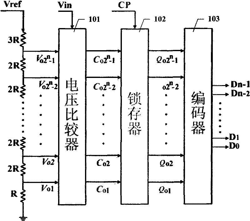
[0010] The purpose of the present invention is to overcome the deficiency of low gain accuracy in the gain correction process of the digital storage oscilloscope in the prior art, and provide a digital storage oscilloscope with high gain control precision, thereby effectively realizing the correction of the digital storage oscilloscope

Method used


Image

  • Digital storage oscilloscope with function of gain calibration
  • Digital storage oscilloscope with function of gain calibration
  • Digital storage oscilloscope with function of gain calibration

Examples


Embodiment

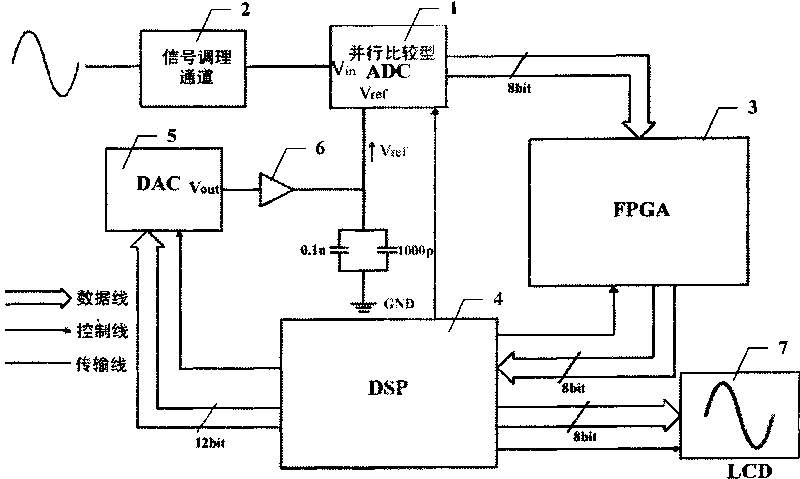
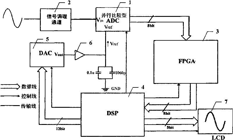
[0029] figure 2 It is a functional block diagram of a specific embodiment of a digital storage oscilloscope with a gain correction function in the present invention.

[0030] like figure 2 As shown, in this embodiment, the digital storage oscilloscope with gain correction function of the present invention includes signal conditioning channel 2, parallel comparison ADC 1, data memory 3, processor 4, DAC 5, buffer 6 and LCD display 7. In this embodiment, the data memory 3 is realized by a FPGA, and the processor 4 is a DSP.

[0031] In this embodiment, the DAC 5 is a 12-bit high-precision high-precision digital-to-analog converter, the input of the DAC 5 is connected to the processor 4, and the output is connected to the parallel comparison ADC 1 reference voltage input terminal V ref , used to receive the 12bit gain control word output by the processor 4, and convert it into a voltage output to the parallel comparison ADC as the reference voltage V for analog-to-digital co...

example

[0036] Taking the 20mv / div file of a digital storage oscilloscope as an example, assuming that the standard reference analog signal is 60mVpp, that is, it should be 3 divisions. In the absence of channel error, the theoretical amplitude value of the signal output by signal conditioning channel 2 is 300mVpp. Parallel comparison ADC 1 Theoretical quantization amplitude value is 75, since the digital storage oscilloscope generally has 25 pixels per division, so the quantization value of 3 divisions is 75. The comparison results of the two gain adjustment methods of the digital storage oscilloscope are shown in Table 1:

[0037]

[0038] Table 1

[0039] It can be drawn from Table 1 that the two-stage gain control method of the present invention eliminates the deviation between the actual quantization value and the theoretical quantization value of the parallel comparison ADC caused by insufficient channel resolution, significantly improves the gain control accuracy, and avoids...


PUM


Abstract

The invention discloses a digital storage oscilloscope with a function of gain calibration, which is characterized by comprising a DAC, wherein the DAC receives gain control words output by a processor, converts the gain control words into voltage, and outputs the voltage to a parallel comparison type ADC serving as the reference voltage of analog-digital conversion. During calibration, the gain control words are changed, so that the reference voltage of the analog-digital conversion of the parallel comparison type ADC is changed, and the quantized value of sampled data is adjusted, and the gain control words are updated until the difference between an actual amplitude quantized value and a theoretical amplitude quantized value is not more than a stated range; and in normal use, the gain control words are sent to the DAC and are converted into the voltage which serves as the reference voltage of the analog-digital conversion, acquisition data output by the analog-digital conversion is sent into a data storage device for storage, and then the acquisition data is read out by the processor for processing and displaying. The invention provides a scheme for adjusting the reference voltage of the analog-digital conversion to perform gain control, which can perform continuous adjustment on gains so as to improve the accuracy of the gain control and effectively achieve the calibration of the digital storage oscilloscope.

Description

technical field [0001] The invention relates to the technical field of digital storage oscilloscopes, in particular to a digital storage oscilloscope with a gain correction function. Background technique [0002] In digital storage oscilloscopes, since the input range of the analog-to-digital converter (ADC) is relatively small, usually around 1Vpp, it is impossible to meet the input range of the oscilloscope as small as a few millivolts and as large as tens of hundreds of volts, so the signal must be designed The conditioning channel performs undistorted conditioning on the analog signal, such as amplifying small signals and attenuating large signals. [0003] With the use environment, such as temperature changes, the aging of the gain amplifier, signal attenuation network and other components, the gain deviation of the digital storage oscilloscope will occur, resulting in a large measurement error, which requires correction of the gain of the digital storage oscilloscope ...

Claims


Application Information

Patent Timeline
IPC IPC(8): G01R13/02
Inventor 叶芃曾浩蒋俊向川云宋建嘉
Owner UNIV OF ELECTRONICS SCI & TECH OF CHINA
Learn More