Plesoelectric ultrasonic flow sensor

A flow sensor, ultrasonic technology, applied in the field of sensors, to solve the problem of performance stability, improve the vibration state, and facilitate the application

Inactive Publication Date: 2010-05-19
AUDIOWELL ELECTRONICS GUANGDONG
View PDF0 Cites 5 Cited by
  • Summary
  • Abstract
  • Description
  • Claims
  • Application Information

AI Technical Summary

Problems solved by technology

Due to the deformation state of the metal shell under the liquid pressure, the sensor chip is bent and deformed, which has a great influence on the performance of the piezoelectric ultrasonic flow sensor, and there is a problem of performance stability under different application conditions, making the piezoelectric ultrasonic flow sensor Ultrasonic flow sensor products are not suitable for various occasions that require ultrasonic flow measurement, so there is a lot of inconvenience in the application of meter manufacturers

Method used


Image

  • Plesoelectric ultrasonic flow sensor
  • Plesoelectric ultrasonic flow sensor
  • Plesoelectric ultrasonic flow sensor

Examples


Embodiment Construction

[0017] The present invention will be further described below in conjunction with accompanying drawing.

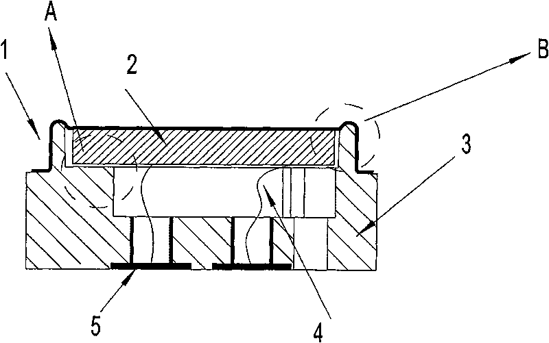
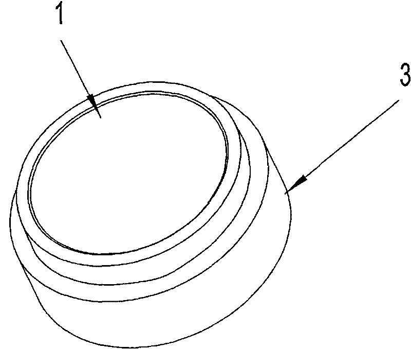
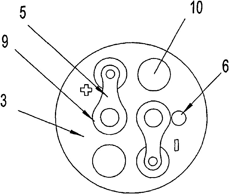
[0018] as attached figure 1 , attached figure 2 , attached image 3 As shown, the piezoelectric ultrasonic flow sensor of the present invention is composed of a metal shell 1, a sensor chip 2, a base 3, a connecting wire 4, and a welding piece 5. The sensor chip is arranged on the metal shell, and the metal shell is installed on the base. The welding piece is installed on the base, and the connecting wire connects the sensor chip and the welding piece. There is an arc-shaped buffer section on the end face of the metal shell, which is bent on the outer edge of the metal shell. The edge bending part is connected with the base, and the arc-shaped buffer section forms elasticity, which improves the deformation state of the end face of the metal shell under the liquid pressure. There are vent holes 6 on the base, which can maintain the balance of the internal and external air...


PUM


Abstract

The invention relates to a plesoelectric ultrasonic flow sensor, belonging to the field of the sensor. The plesoelectric ultrasonic flow sensor consists of a metal shell, wafers, a base, connecting leads and welding pieces. The wafers are arranged on the metal shell; the metal shell is arranged on the base; the welding pieces are arranged on the base; the connecting leads are used for connecting the wafers with the welding pieces; and the end surface of the metal shell is provided with an arc-shaped buffering section which can form elasticity to improve the deforming state of the end surface of the metal shell under liquid pressure. The plesoelectric ultrasonic flow sensor has reasonable structural design, and the problem concerning the stability of the performance of the plesoelectric ultrasonic flow sensor under different application condition is effectively solved so that the plesoelectric ultrasonic flow sensor can be applied conveniently to various occasions needing the plesoelectric ultrasonic flow sensor.

Description

technical field [0001] The piezoelectric ultrasonic flow sensor of the invention belongs to the field of sensors. Background technique [0002] Piezoelectric ultrasonic flow sensor is the core component of the current international ultrasonic flowmeter, which is composed of metal shell, sensor chip, base, connecting wire, soldering piece, the sensor chip is set on the metal shell, and the metal shell is installed on the base On the base, the solder tab is installed on the base, and the connecting wire connects the sensor chip and the solder tab. Due to the deformation state of the metal shell under the liquid pressure, the sensor chip is bent and deformed, which has a great influence on the performance of the piezoelectric ultrasonic flow sensor, and there is a problem of performance stability under different application conditions, making the piezoelectric ultrasonic flow sensor Ultrasonic flow sensor products are not suitable for various occasions that require ultrasonic ...

Claims


Application Information

Patent Timeline
Patent Type & Authority Applications(China)
IPC IPC(8): G01F1/66G01F15/00
Inventor 张曙光陈廷富
Owner AUDIOWELL ELECTRONICS GUANGDONG
Why Eureka
Try Eureka