Electronic equipment and its circuit board assembly
A circuit board assembly and circuit board technology, applied in the direction of circuits, printed circuits, printed circuits, etc., can solve problems such as legacy motherboards or circuit boards, short circuits of electronic devices, safety accidents of the whole machine, etc., achieve good deformation state, and improve stress situation, the effect of uniform force
- Summary
- Abstract
- Description
- Claims
- Application Information
AI Technical Summary
Problems solved by technology
Method used
Image
Examples
Embodiment 1
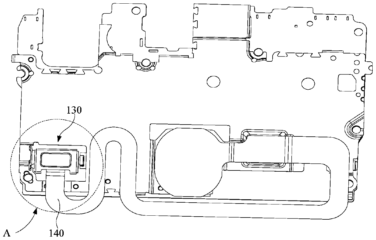
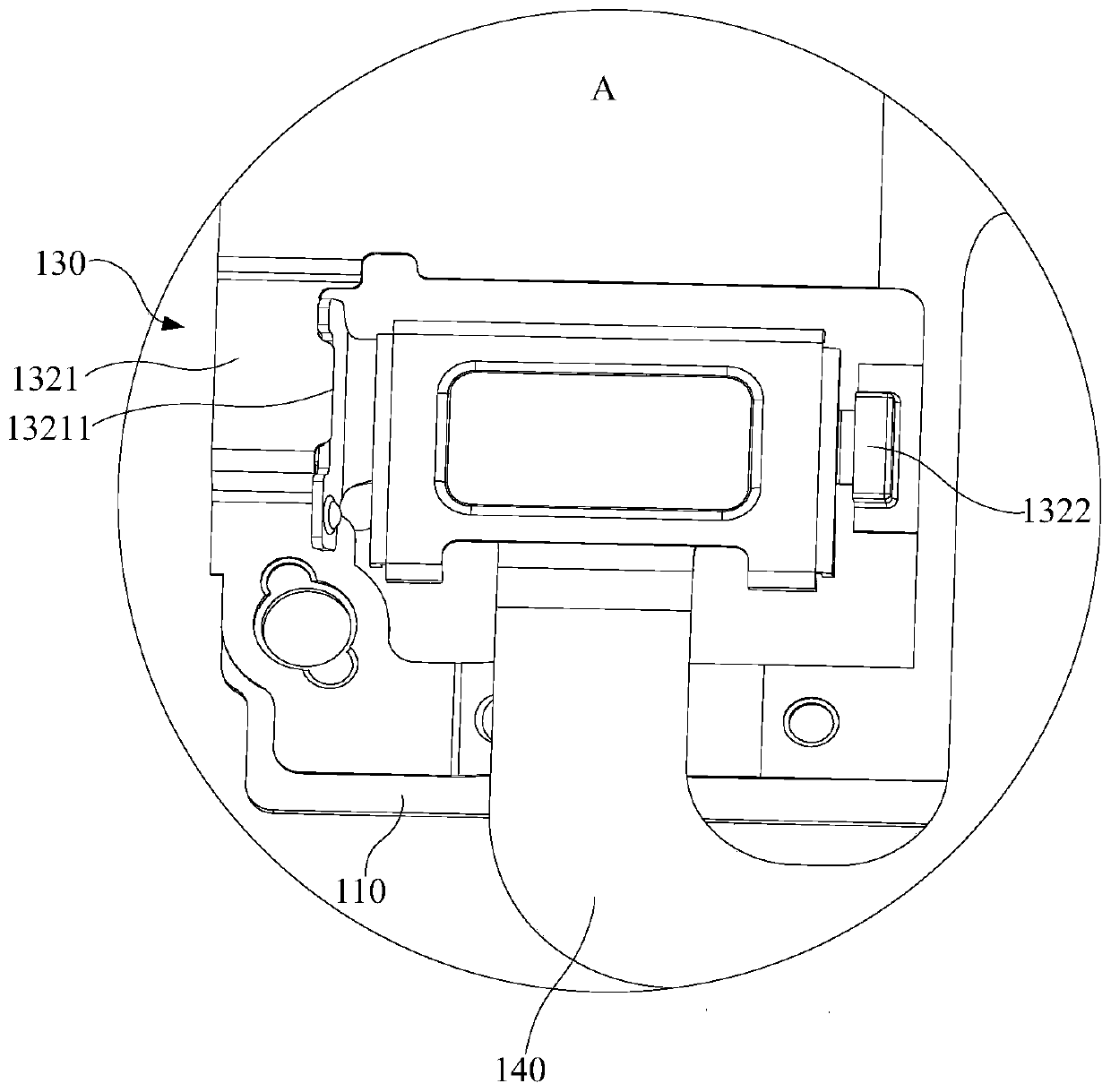
[0025] Please also refer to figure 1 and figure 2 , figure 1 It is a schematic diagram of the overall structure of an embodiment of a circuit board assembly for electronic equipment in this application, figure 2 yes figure 1 An enlarged schematic diagram of a partial structure of the circuit board assembly in the embodiment; it should be noted that the electronic devices in this application may include mobile phones, tablet computers, notebook computers, desktop computers, wearable devices and other electronic devices with BTB connectors. The circuit board assembly for electronic equipment in this embodiment includes a circuit board 110 , a BTB connector 120 and a pressing board assembly 130 .
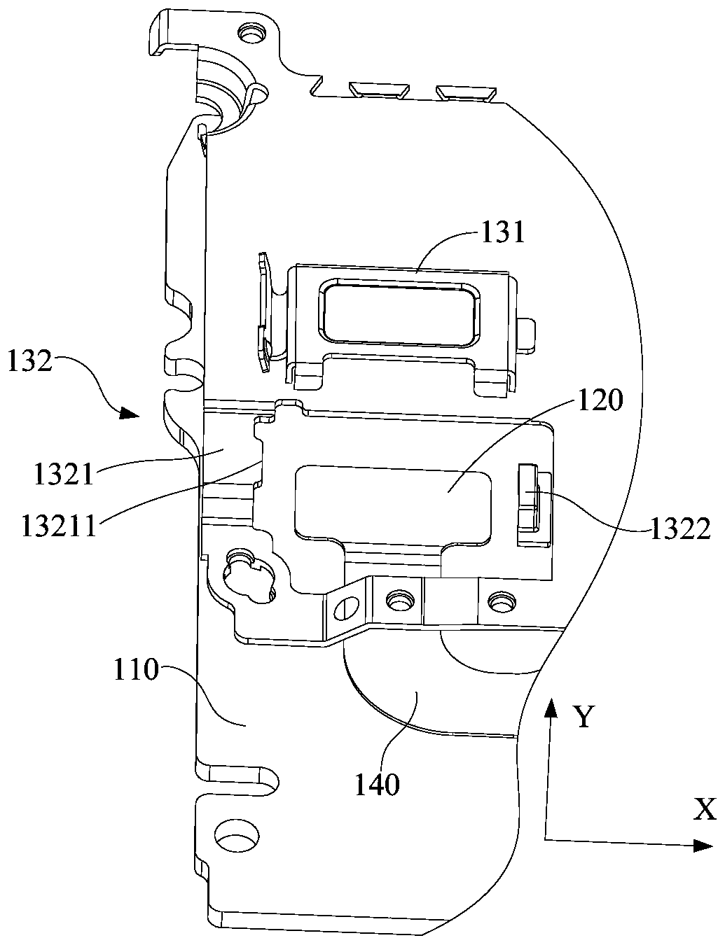
[0026] Further, see image 3 , image 3 yes figure 1 An enlarged schematic diagram of partial disassembly of the circuit board assembly in the embodiment; the BTB connector 120 is fixed on the circuit board 110, the BTB connector 120 can be connected to the flexible cable 140, ...
Embodiment 2
[0042] see Figure 8 , Figure 8 It is an enlarged schematic view of the local structure of another embodiment of the circuit board assembly of the present application. The first auxiliary pressure plate 1321 is provided with a raised portion 13211 on the side close to the first clamping portion 1312, and the second side wall 13123 supports the first auxiliary pressure plate 1321. One side of the pressure plate 1321 is provided with a notch 131231, and the protrusion 13211 is inserted into the notch 131231 in the first direction. The difference from the previous embodiment is that in this embodiment, the protrusion 13211 of the first auxiliary pressure plate 1321 is provided with a notch 13212, there is a gap 101 between the notch 13212 and the outer surface of the second side wall 13123 of the first clamping part 1312, and the gap 101 is used to accommodate the insert (not shown in the figure, the insert is not in the technical solution of this application) contained structu...
Embodiment 3
[0045] Please also refer to image 3 , Figure 4 as well as Figure 9 , Figure 9 yes Figure 4 The structural diagram of the main pressure plate in another perspective in the embodiment, the side of the main body portion 1311 of the main pressure plate 131 is provided with a shielding portion 1314 extending toward the side of the BTB connector 120, and the shielding portion 1314 is used to protect the BTB connector 120 from the side Protect. Optionally, the extending direction of the shielding portion 1314 may be a direction perpendicular to the plane where the main body portion 1311 is located, that is, the third direction mentioned above.
[0046] Optionally, in this embodiment, the main body portion 1311 is rectangular in shape, and an avoidance gap 102 is provided between the shielding portions 1314 connected to adjacent sides. The avoidance gap 102 is set at a corner position, and the function of the avoidance gap 102 is : The main pressure plate is formed by one-pi...
PUM
 Abstract
Description
Claims
Application Information
 - R&D
- Intellectual Property
- Life Sciences
- Materials
- Tech Scout
- Unparalleled Data Quality
- Higher Quality Content
- 60% Fewer Hallucinations
Browse by: Latest US Patents, China's latest patents, Technical Efficacy Thesaurus, Application Domain, Technology Topic, Popular Technical Reports.
© 2025 PatSnap. All rights reserved.Legal|Privacy policy|Modern Slavery Act Transparency Statement|Sitemap|About US| Contact US: help@patsnap.com


