Reactor unit

A technology for reactors and electrical terminals, applied in the direction of inductors, electrical components, fixed inductors, etc., can solve problems such as difficult operation, high soldering cost, and poor contact

Active Publication Date: 2010-05-19
PANASONIC CORP
View PDF1 Cites 5 Cited by
  • Summary
  • Abstract
  • Description
  • Claims
  • Application Information

AI Technical Summary

Problems solved by technology

[0006] However, in the existing electrical connection device between the aluminum winding coil and the copper wire, the aluminum wire cannot be fixed on the copper electrical terminal with ordinary solder, so it is necessary to use a special solder material for aluminum wire, which will cause Problems such as higher cost than usual solder and diff

Method used


Image

  • Reactor unit
  • Reactor unit
  • Reactor unit

Examples


Embodiment Construction

[0019] An embodiment of the present invention will be described in detail below with reference to the accompanying drawings. At the same time, it should be pointed out that the embodiments of the present invention do not limit the scope of the present invention.

[0020] (Example)

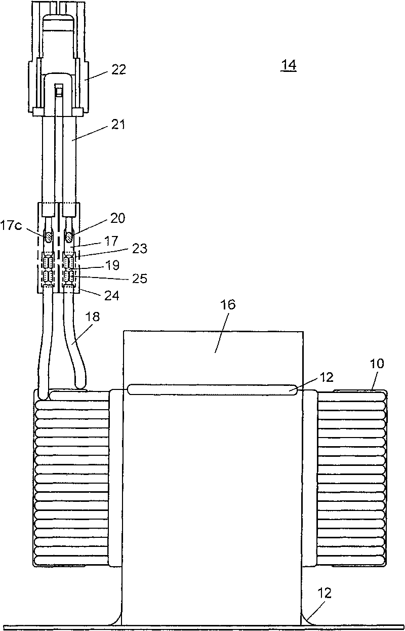
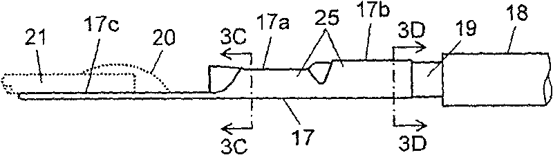
[0021] Refer below Figure 1 ~ Figure 4 The reactor unit of this embodiment will be described. The reactor unit of this embodiment is used to suppress the high-frequency current in the washing machine and the like for frequency conversion control, and improve the power factor. The winding coil uses aluminum wire, and the power input part uses copper wire. Between the winding coil and the copper wire Equipped with electrical connections.

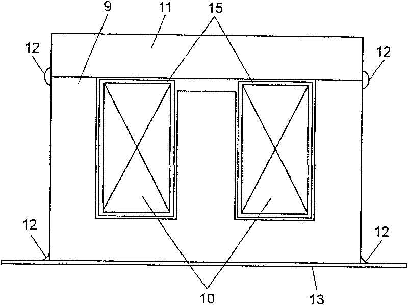
[0022] figure 1 is a sectional view of the reactor unit in this embodiment. Such as figure 1 As shown, the electromagnetic thin steel plate is punched into the shape of the English letter "E" by a stamping die, and then laminated / welded to form an E-shaped...


PUM


Abstract

A reactor unit includes a winding coil having aluminum wires wound around an iron core, and a copper-made electric terminal connected to end parts of the winding coil, in which the electric terminal has a pressing and connecting part for pressing and connecting aluminum wires of the winding coil at one end, and a welding part of a nearly flat shape at other end, so that the electrical connection between dissimilar materials is realized at low cost and high reliability.

Description

technical field [0001] The present invention relates to a reactor used in electric and electronic equipment, and more specifically, to a reactor unit provided with an electrical connection device between a winding coil formed by winding an aluminum wire and a copper wire. Background technique [0002] Japanese Patent Laid-Open Publication No. 1995-22258 shows an existing reactor with an electrical connection device between the winding coil and the copper wire, Figure 5 It is the front view of the existing reactor. [0003] Such as Figure 5 As shown, an iron core 2 is installed on an iron base 1, and a winding coil 4 is installed on the iron core 2. The winding coil 4 is wound with an aluminum wire 3 sintered with a paint film on the surface, and the entire reactor needs to be dipped in paint. deal with. The reason why the winding coil 4 is composed of the aluminum wire 3 made of aluminum is that the aluminum wire 3 is cost-effective compared to the copper wire. In recent ...

Claims


Application Information

Patent Timeline
IPC IPC(8): H01F27/29H01R43/16
CPCH01R4/023H01R4/72H01R4/184H01R11/16H01F37/00H01F27/29H01F27/2828H01R4/029H01R4/62H01R4/187
Inventor 柳真介松尾繁
Owner PANASONIC CORP
Why Eureka
Try Eureka