Turbine rotor and power plant

A technology for turbine rotors and power generation equipment, which is applied to mechanical equipment, wind power generation, hydropower generation, etc., and can solve problems such as large-diameter hubs with closed and hollow anti-torque sections

Inactive Publication Date: 2010-05-19
斯维涡轮公司
View PDF6 Cites 13 Cited by
  • Summary
  • Abstract
  • Description
  • Claims
  • Application Information

AI Technical Summary

Problems solved by technology

With regard to these prior art documents mentioned above, there is no mention of a large-diameter hub with a closed and hollow torsion-resistant section, on which the blades of the turbine rotor are arranged

Method used


Image

  • Turbine rotor and power plant
  • Turbine rotor and power plant
  • Turbine rotor and power plant

Examples


Embodiment Construction

[0102] In the following, a first embodiment of the invention relates to an embodiment in which the donut-shaped hub is at least partly supported on the stator by means of a magnetic bearing, as shown for example in Figure 6 and 7 , a second embodiment of the invention relates to an embodiment in which a hub in the shape of a donut is supported on a central hub, such as Figure 8 shown.

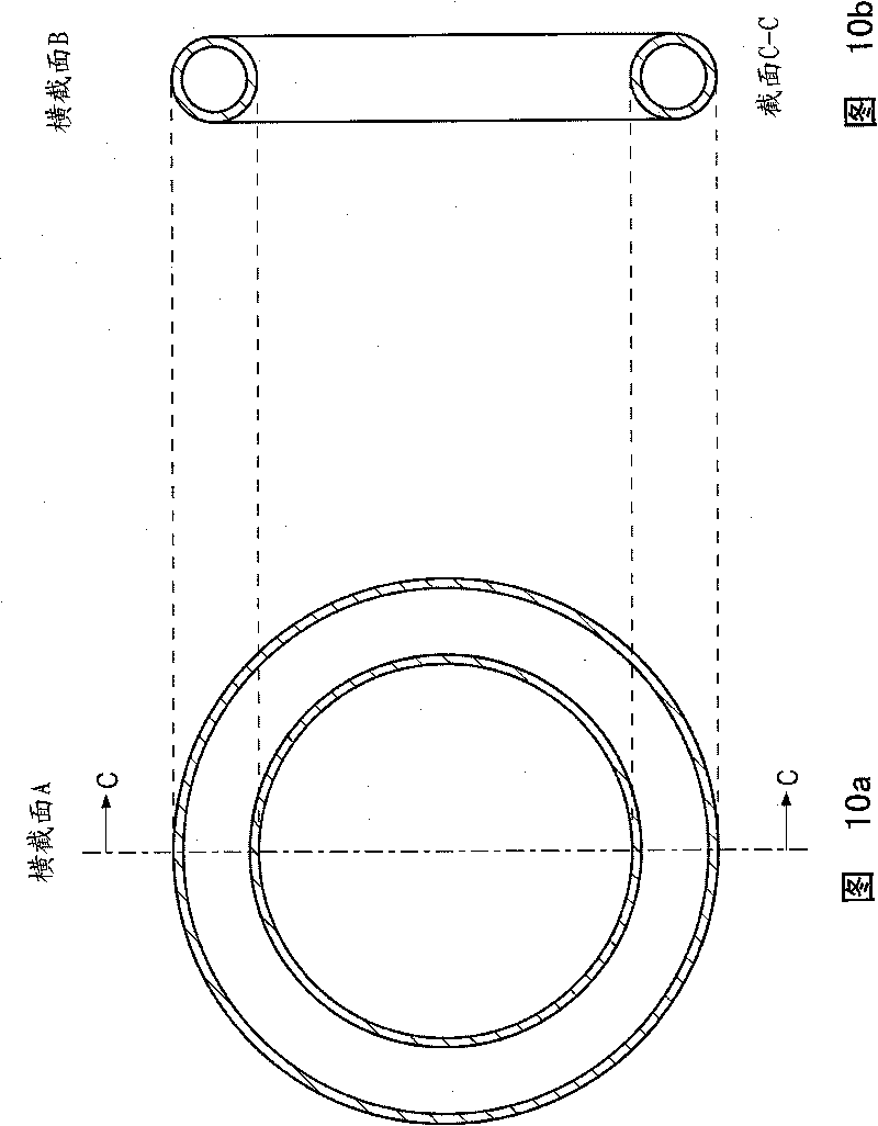
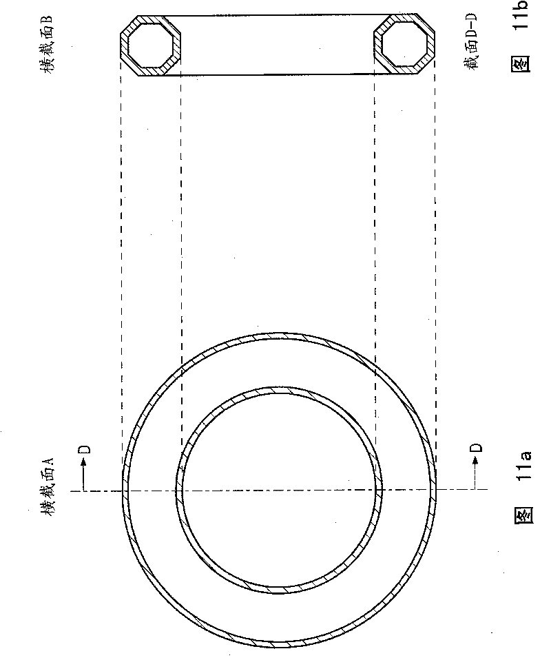
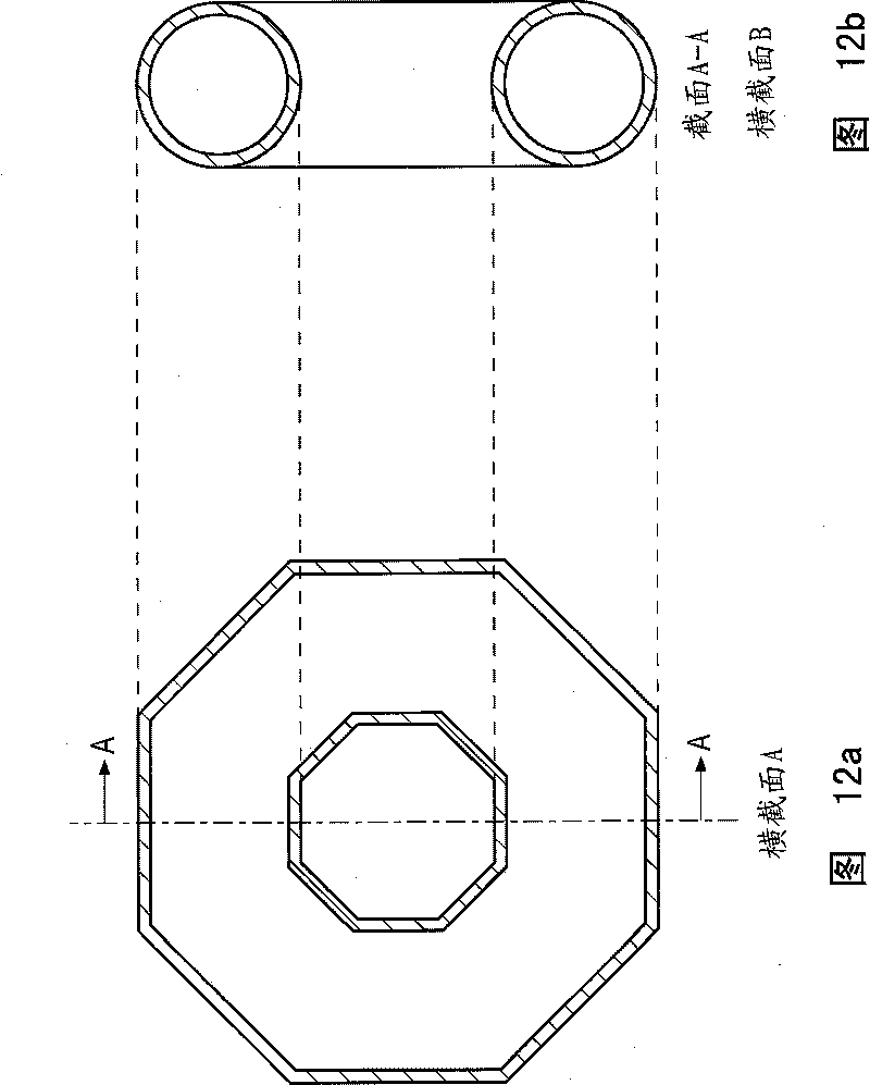
[0103] figure 1 Shown is a wind power plant 1 with an output of 10-12 MW equipped with a large generally donut-shaped hub 6, 105, wherein the donut-shaped hub may have a diameter of about 20 metres. The donut-shaped hub 6, 105 may have a diameter in cross-section B of approximately 3 meters. The rotor blades 3, 4, 5 may each have a length of 60 m and are mounted on pitch bearings 8, 9, 10 as figure 2 As shown, the pitch bearing is arranged to enable rotation of the blade about its longitudinal axis in response to a push from a pitch control system (not shown). For example Figure 8 As...


PUM


Abstract

A turbine rotor for a wind or hydropower plant or for propulsive means for a vessel where the turbine rotor comprises a generally doughnut-shaped hub. The doughnut-shaped hub is configured as a closed, hollow profile in a cross section B, and wherein the doughnut-shaped hub is formed either in the shape of a torus, the torus being circularly shaped in cross section B and the torus being ring-shaped in cross section A wherein the outer and inner circumferences of the ring are circular, or in the shape of a quasi-torus, the quasi-torus being polygonally or circularly shaped in cross section B and the torus being ring-shaped in cross section A wherein the outer and inner circumferences of the ring are polygonally or circularly shaped, on which torus or quasi-torus at least one rotor blade is provided. There is also provided a wind, hydro or tidal plant comprising the turbine rotor.

Description

technical field [0001] The invention relates to a turbine rotor for a wind, hydro or tidal power plant, and a wind or hydro power plant comprising such a turbine rotor. The invention also relates to the use of the turbine rotor in a wind or hydroelectric power plant, or as a shipboard propulsion device. Briefly, in front view, the turbine rotor consists of a large diameter, substantially "donut-shaped" or ring-shaped rotor hub supported by a closed, hollow, torque-resistant A profile (profile) on which the rotor blades are arranged. Background technique [0002] Windmills or wind turbines for generating power, preferably in the form of electricity, are continually being developed in the direction of larger mills. Windmills with an output of about 5MW and rotor diameters greater than 115-125m have now been designed and built. Windmills equal to and larger than 5MW are mainly designed for offshore installation because such large windmills are difficult to transport on land....

Claims


Application Information

Patent Timeline
Patent Type & Authority Applications(China)
IPC IPC(8): F03D1/06F03D11/00F03D11/04
CPCY02E10/725F05B2240/50F03D1/0608Y02E10/28F03D11/00F03D11/04Y02E10/728F05B2210/16Y02E10/721F03D1/06F03D1/0666F16C2360/31F16C32/0406F03D80/00F03D13/20F03D1/0691Y02E10/30Y02E10/72F03D1/0658Y02E10/20F03D80/70F03D15/10F03D9/25F03D9/32
Inventor E·博金
Owner 斯维涡轮公司
Why Eureka
Try Eureka