
Washing machine

A washing machine and detergent technology, applied in the field of washing machines, can solve problems such as detergent residue, cost increase, and lifespan of seals

Active Publication Date: 2010-05-26
PANASONIC CORP
View PDF1 Cites 11 Cited by
  • Summary
  • Abstract
  • Description
  • Claims
  • Application Information

AI Technical Summary

Problems solved by technology

[0008] However, in the structure where the seal is installed, not only the assembly process is complicated and the cost increases, but also the life of the seal is problematic.
In addition, in the structure in which the bypass water discharge hole is set on the water injection cover 66 to reduce the water discharge pressure of the detergent storage container, if the water pressure is low, the amount of water supplied to the detergent storage container will become too small.
Disadvantage of detergent residue when detergent cannot be completely dissolved / flowed out

Method used


Image

  • Washing machine
  • Washing machine
  • Washing machine

Examples


Embodiment 1

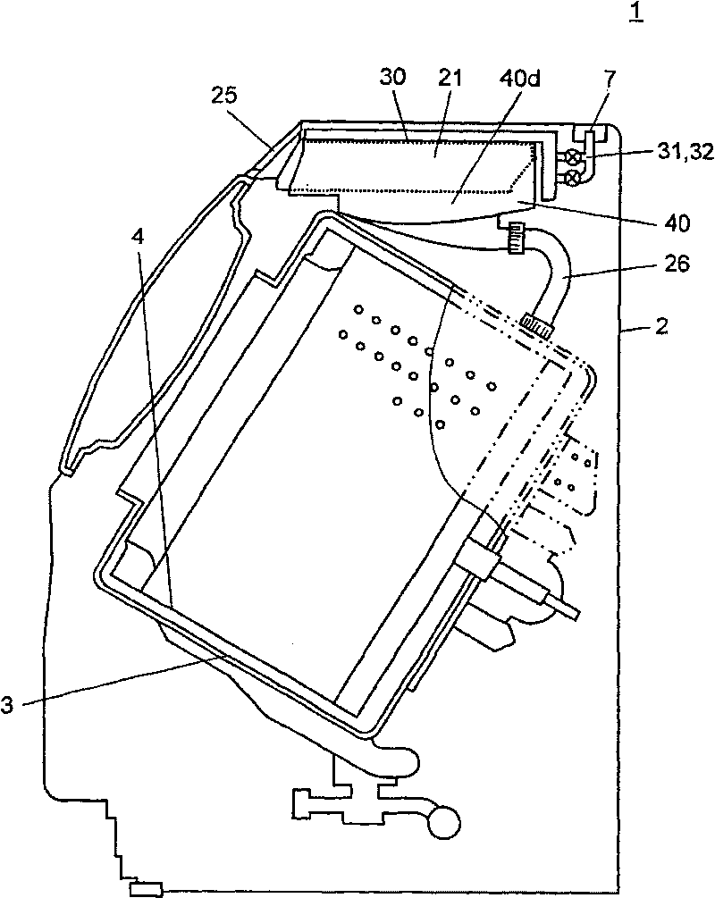
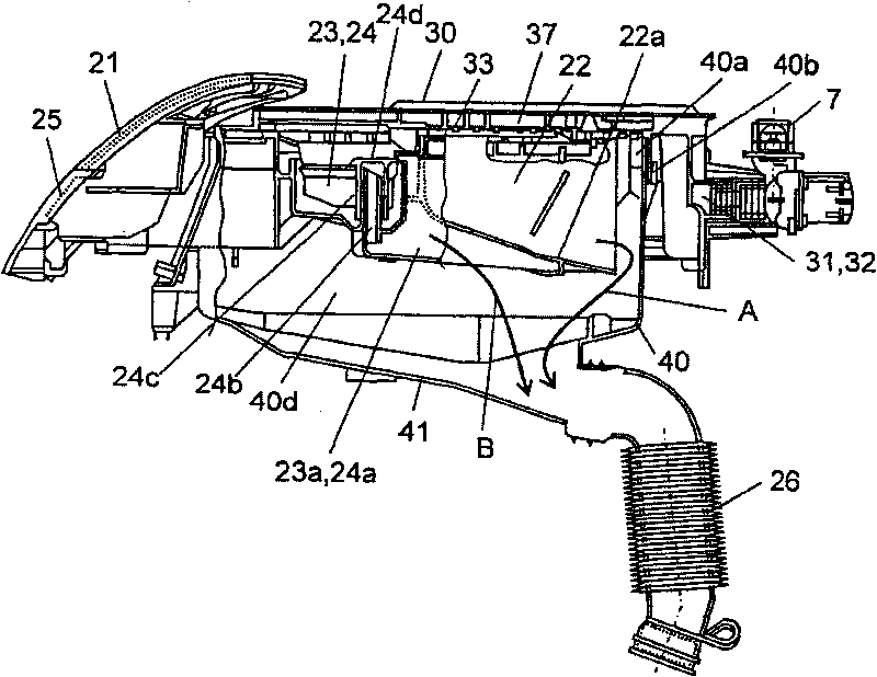
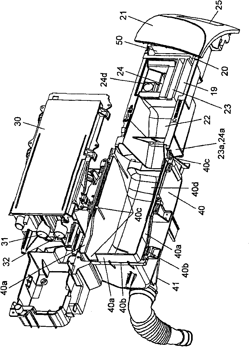
[0021] figure 1 It is a longitudinal sectional view of the washing machine in Example 1 of the present invention. exist figure 1 In the middle, the left is the front of the washing machine, figure 2 is a side sectional view of the housing portion of the detergent dispenser in the washing machine, image 3 It is an exploded oblique view of the shell part of the detergent dispenser in the washing machine.

[0022] like figure 1 As shown in , the washing machine 1 has a washing machine frame body 2, and a water holding cylinder 3 and a rotating drum 4 are arranged in the washing machine frame body 2. A detergent dispenser housing 40 is provided above the water storage cylinder 3, and the upper opening of the detergent dispenser housing 40 is a box body with a bottom surface and a cross-section roughly in the shape of "]". In addition, a water injection cover 30 is provided above the detergent dispenser housing 40 . The detergent storage container 21 is accommodated in t...

Embodiment 2

[0047] Use below Figure 5 The structure and operation of Embodiment 2 of the present invention will be described. For the sake of brevity, the description of the same parts as those in Embodiment 1 is omitted here, and only the different parts are described.

[0048] Figure 5 It is an exploded perspective view of the shell of the detergent dispenser of the washing machine in the second embodiment of the present invention, where the detergent storage container 21 is pulled out beyond the specified position and the water injection cover 30 is turned upside down. Oblique view.

[0049] like Figure 5 As shown in , a liquid detergent storage container 23 and a liquid softener storage device 24 are arranged in parallel in the detergent storage container 21 . In addition, in front of the liquid detergent storage container 23 and the liquid softener storage container 24 ( Figure 4 On the right side) and the handle 25, there is a concave recovery groove 50 with a bottom. The ...


PUM


Abstract

The invention discloses a washing machine which comprises the following components: a washing agent container; a filler cover that that fills the washing agent container; a washing agent dispenser housing; and a water supply path with one end communicates with a water supply valve and the other end communicates with a water barrel. The washing agent container comprises the following components: a washing agent container; an inlet path that communicates with space of the washing agent; a concave reclamation groove with a bottom on drawing out direction of the washing agent container; and a reclamation passage communicates with the reclamation groove. The reclamation passage communicates with the inlet path. With such structure, problem of leak in drawing out direction of the washing agent container can be solved, water supply quantity to the washing agent container can be increased, and washing agent residence when supplying water at low pressure can be solved.

Description

technical field [0001] The present invention relates to a washing machine provided with a detergent storage container and a water filling cover for supplying water into the detergent storage container. Background technique [0002] The water supply mechanism in the existing washing machine is generally that a water supply valve is provided on the upper part of the body of the washing machine, and the water from the tap water pipe first enters the water supply valve, and then supplies water to the water storage cylinder through a detergent storage container equipped with detergent (one example can be See Japanese Patent Laid-Open Publication No. 2007-68801). [0003] Image 6 It is a longitudinal cross-sectional view of a conventional drum-type washing machine. Figure 7 It is a side view showing the structure of a detergent storage container in a conventional drum-type washing machine. [0004] exist Image 6 Among them, the drum type washing machine 60 is provided with: a...

Claims


Application Information

Patent Timeline
IPC IPC(8): D06F39/02D06F39/08
Inventor 神藤健前田一宪奥山武人
Owner PANASONIC CORP
Learn More