temporary water supply system

A temporary water supply and water pump technology, applied in water supply pipeline systems, water supply devices, water supply main pipelines, etc., can solve the problems of less water supply equipment, waste of manpower, fast depreciation of water pumps, etc., and achieve good work stability, water saving, and maintenance costs. low effect

Active Publication Date: 2018-03-27
CHINA METALLURGICAL CONSTR ENG GRP
View PDF9 Cites 0 Cited by
  • Summary
  • Abstract
  • Description
  • Claims
  • Application Information

AI Technical Summary

Problems solved by technology

In the actual construction and operation process, due to the insufficient water pressure of the municipal water supply, the normal water supply cannot be carried out during high-altitude operations, so a complete set of water pump pressurization control system is required to supply water normally
However, there are relatively few water supply equipment in the market that can meet the needs of construction sites, and it is difficult to realize the characteristics of water conservation and water supply at high places.
The existing electronic control system is easily damaged and difficult to maintain. The relay and contactor control systems are not suitable for construction sites. In addition, the water supply system on the construction site is manually controlled, that is, the pump is turned on when the water is used, and the pump is stopped when the water is not used. This wastes manpower. , a waste of electric energy, and the depreciation of the water pump is fast

Method used


Image

  • temporary water supply system
  • temporary water supply system

Examples


Embodiment Construction

[0023] The following will clearly and completely describe the technical solutions in the embodiments of the present invention with reference to the accompanying drawings in the embodiments of the present invention. Obviously, the described embodiments are only some, not all, embodiments of the present invention. Based on the embodiments of the present invention, all other embodiments obtained by persons of ordinary skill in the art without making creative efforts belong to the protection scope of the present invention.

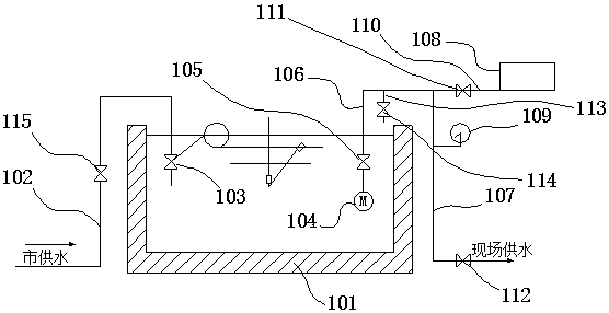
[0024] See figure 1 and figure 2 , the temporary water supply system of the present invention includes a reservoir 101, a water inlet pipe 102, a float level valve 103, a water pump 104 (which may be a clear water submersible pump 104), a main water outlet pipe, a check valve 105, and a pressure storage and stabilization device 108, an electric contact pressure gauge 109 and a water pump control device for controlling the operation of the water pump 104; the...


PUM


Abstract

The invention discloses a temporary water supply system. The system comprises a reservoir, a water inlet pipeline, a floating ball liquid level valve, a water pump, a main water outlet pipeline, a check valve, a pressure storage and stabilizing device, a pressure gauge with electric contact and a water pump control device used for controlling the water pump to work, wherein the water inlet pipeline is used for leading an external water source into the reservoir; the water inlet end of the water inlet pipeline is connected with the external water source, and the water outlet end is connected with the floating ball liquid level valve in the reservoir; the water pump is arranged in the reservoir; a water outlet of the water pump is communicated with the water inlet end of the main water outlet pipeline; the check valve is arranged in the position, close to the water inlet end, on the main water outlet pipeline; the pressure storage and stabilizing device is communicated with the main water outlet pipeline to provide stable water pressure for the main water outlet pipeline; the pressure gauge with electric contact is communicated with the main water outlet pipeline and is arranged between the water outlet end of the main water outlet pipeline and the pressure storage and stabilizing device; and the pressure gauge with electric contact and the floating ball liquid level valve are also electrically connected with the water pump control device.

Description

technical field [0001] The invention relates to a water supply system, in particular to a temporary water supply system for building engineering construction. Background technique [0002] Temporary construction water consumption includes: on-site construction water consumption, construction machinery water consumption, construction site domestic water consumption, living area domestic water consumption, fire protection water consumption, etc., and on-site construction water consumption is the main part of construction temporary water consumption. In the actual construction and operation process, such a situation was encountered. Due to the insufficient water pressure of the city, the normal water supply could not be carried out during high-altitude operations, so a complete set of water pump pressurization control system was required to supply water normally. However, there are relatively few water supply equipment available on the market, and it is difficult to realize the...

Claims


Application Information

Patent Timeline
Patent Type & Authority Patents(China)
IPC IPC(8): E03B11/16E03B7/07F04B49/06
CPCE03B7/07F04B49/06
Inventor 刘友力席兵
Owner CHINA METALLURGICAL CONSTR ENG GRP
Why Eureka
Try Eureka