Eye space positioning device

A space positioning and eye technology, which is applied in the direction of measuring devices, optical devices, instruments, etc., can solve the problems that it is difficult to make portable instruments for embedded control systems, restrictions on the movement of the subjects, complex and expensive systems, etc., and achieve low requirements for incident light beams , high positioning accuracy and simple system structure

Inactive Publication Date: 2010-05-26
UNIV OF SHANGHAI FOR SCI & TECH
View PDF0 Cites 3 Cited by
  • Summary
  • Abstract
  • Description
  • Claims
  • Application Information

AI Technical Summary

Problems solved by technology

However, the current eye tracking system still has some technical problems: when using a non-helmet system, the system is complex and expensive, has poor real-time performance, has high environmental requirements, and has certain restrictions on the movement of the subjects; , and make users feel uncomfortable
The above methods usually require the use of high-calculation algorithms such as pattern recognition and template matching, so it is difficult to make embedded control systems and portable instruments

Method used


Image

  • Eye space positioning device
  • Eye space positioning device
  • Eye space positioning device

Examples


Embodiment Construction

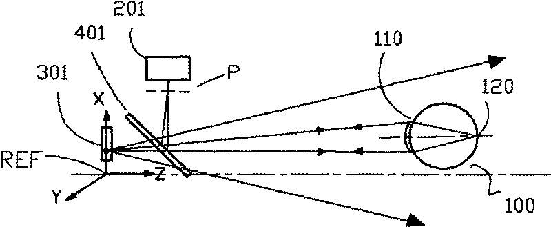
[0018] Such as figure 1 The principle diagram of light reflection from the retina of the eye and the generation of reflection spots is shown. The eye 100 is generally not located on the coordinate axes of the reference coordinate system XYZ; Enters the eye 100 after transmission. The human eye 100 is a complete optical system, and the eye 100 can be simply abstracted into an optical model, the lens can be equivalent to a convex lens, and the retina is equivalent to a light screen. The light that enters the eye 100 is imaged on the retina 120 through the lens 110, and the light can be reflected by the retina; the reflected light beam is modulated by the lens 110, and returns according to the original optical path; Form the image of a point light source, the image of the point light source is conjugate with the point light source of the lighting unit 301 with respect to the semi-transparent mirror 401, the image of the point light source has nothing to do with the position and ...


PUM


Abstract

The invention relates to an eye space positioning device. The device comprises at least one point light source of an illuminating unit; part of light energy enters eyes after being transmitted by at least one semitransparent reflector; the light returns to the semitransparent reflector in the same route and is reflected on at least one imaging unit to form an image of the point light source; and an acquisition system acquires a position of the point light source in a reference coordinate system and a position of the image of the point light source, and calculates to obtain a position of the eyes in the reference coordinate system. The eye space positioning device can realize the detection of the space position and the state of the eyes by an optical method, has no limit on background light, has low requirement on an incident beam, has wide system application range, realizes real-time signal output, and has high positioning accuracy, convenient use, high stability and reliability, simple system structure and low cost.

Description

technical field [0001] The invention relates to the field of photoelectric detection, in particular to an eye space positioning device. Background technique [0002] Current eye-tracking systems usually use infrared rays to capture the reflections of the cornea and retina, and there are two ways, helmet-mounted and non-helmet-mounted. Modern eye-tracking systems have become easier to operate and less time-consuming than the original eye-tracking systems. However, the current eye tracking system still has some technical problems: when using a non-helmet system, the system is complex and expensive, has poor real-time performance, has high environmental requirements, and has certain restrictions on the movement of the subjects; , it will make the user feel uncomfortable. [0003] It can be said that the non-helmet system is the current and future development direction of the eye tracking positioning system. Existing non-helmet systems usually use image processing methods to ...

Claims


Application Information

Patent Timeline
Patent Type & Authority Applications(China)
IPC IPC(8): G01B11/00
Inventor 郭汉明蓝景恒丁左红翁晓羽满忠胜庄松林
Owner UNIV OF SHANGHAI FOR SCI & TECH
Why Eureka
Try Eureka