
Electronic tag infrared positioning system

A technology of electronic tags and positioning systems, applied in the field of RFID technology, can solve the problems of large external environment influence, short service life of batteries and infrared tubes, no uniqueness of reader tag signals, etc., and achieve the effect of increasing service life

Inactive Publication Date: 2010-05-26
周必友
View PDF0 Cites 15 Cited by
  • Summary
  • Abstract
  • Description
  • Claims
  • Application Information

AI Technical Summary

Problems solved by technology

[0005] The purpose of the present invention is to provide a new type of electronic tag infrared positioning that can solve the problems that the existing infrared positioning technology is greatly affected by the external environment, the reader has no uniqueness in receiving tag signals, and the service life of the battery and infrared tube is short. system

Method used


Image

  • Electronic tag infrared positioning system
  • Electronic tag infrared positioning system
  • Electronic tag infrared positioning system

Examples


Embodiment Construction

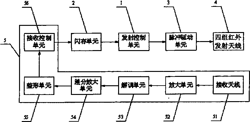
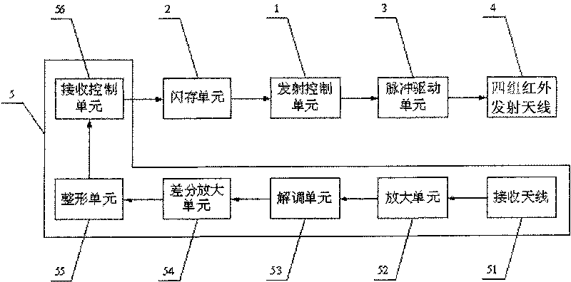
[0010] The specific embodiment of the present invention proposes a kind of infrared reader-writer, as figure 1 As shown, it can be composed of a transmission control unit 1, a flash memory unit 2, a pulse drive unit 3, an infrared transmission antenna 4 and a microwave receiving demodulation unit 5, and the data output terminal of the flash memory unit 2 is connected to the data input terminal of the transmission control unit 1 , the data output end of the emission control unit 1 is connected with the data input end of the pulse drive unit 3, the data output end of the pulse drive unit 3 is connected with the data input unit of the infrared transmitting antenna 4, and the data output of the microwave receiving demodulation unit 5 The terminal is connected with the data input terminal of the flash memory unit 2.

[0011] The working principle of the reader-writer is: when the reader-writer is powered on, the launch control unit 1 reads the device number (8BIT) and launch cycle ...


PUM


Abstract

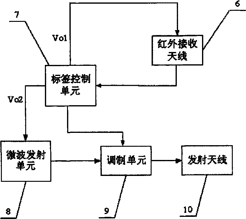
The invention relates to an electronic tag infrared positioning system, and belongs to the field of RFID technical application. The electronic tag infrared positioning system solves the problems that the conventional infrared positioning technology is influenced by external environment greatly, tag signals received by a reader-writer are not unique and a battery and a high-power infrared pipe are short in service life. A flash memory unit of the reader-writer is connected with a transmitting control unit which is connected with a pulse driving unit; the pulse driving unit is connected with an infrared transmitting antenna; a microwave receiving and demodulating unit is connected with a reader-writer control unit; an infrared receiving antenna of an electronic tag is connected with a tag control unit; two control ends of the tag control unit are respectively connected with the infrared receiving antenna and a microwave transmitting unit; the microwave transmitting unit is connected with a modulation unit; the modulation unit is connected with the tag control unit; and the modulation unit is connected with the transmitting antenna. The infrared positioning technology of the invention is not interfered by the external environment, the service life of the battery and the infrared pipe are prolonged, and simultaneously, the infrared positioning technology can provide the unique signal for the tag received by the reader-writer.

Description

technical field [0001] The invention relates to an infrared positioning system composed of a reader-writer and an electronic label, belonging to the field of RFID technology application. Background technique [0002] The main working principle of the infrared positioning technology currently applied to the electronic label is that the reader continuously emits meaningless infrared signals. After the electronic label enters the effective receiving area, the infrared receiving head on the label receives the infrared signal, and then triggers the microwave emission system. Transmit FSK microwave signals (carriers mainly include 433MHZ and 2.4GHZ). The microwave receiving device on the reader receives and demodulates the data information of the tag. [0003] Since the infrared receiving unit is susceptible to interference from various external infrared sources, the electronic tag is often triggered by mistake, resulting in a large change in the working distance of the tag (from...

Claims


Application Information

Patent Timeline
Patent Type & Authority Applications(China)
IPC IPC(8): G06K7/10G06K19/07
Inventor 周必友
Owner 周必友
Learn More