Tri-spindle synchronizer

A synchronization device and spindle technology, applied in the direction of fluid pressure actuators, servo motors, mechanical equipment, etc., can solve the problems of difficult operation and difficulty in ensuring synchronization, so as to improve precision and production efficiency, high synchronization accuracy, The effect of stable and consistent feed speed

Inactive Publication Date: 2013-03-27
山东省青岛生建机械厂
View PDF0 Cites 0 Cited by
  • Summary
  • Abstract
  • Description
  • Claims
  • Application Information

AI Technical Summary

Problems solved by technology

Since the three spindles are affected by factors such as resistance, impact, or system pressure changes during the movement, the distribution of oil volume also changes accordingly, and the synchronization is difficult to guarantee.
Due to the many uncertain factors in the hydraulic system itself, coupled with the influence of human adjustment errors and other factors, it is quite difficult to operate to ensure the synchronization accuracy of the three spindles

Method used


Image

  • Tri-spindle synchronizer
  • Tri-spindle synchronizer
  • Tri-spindle synchronizer

Examples


Embodiment Construction

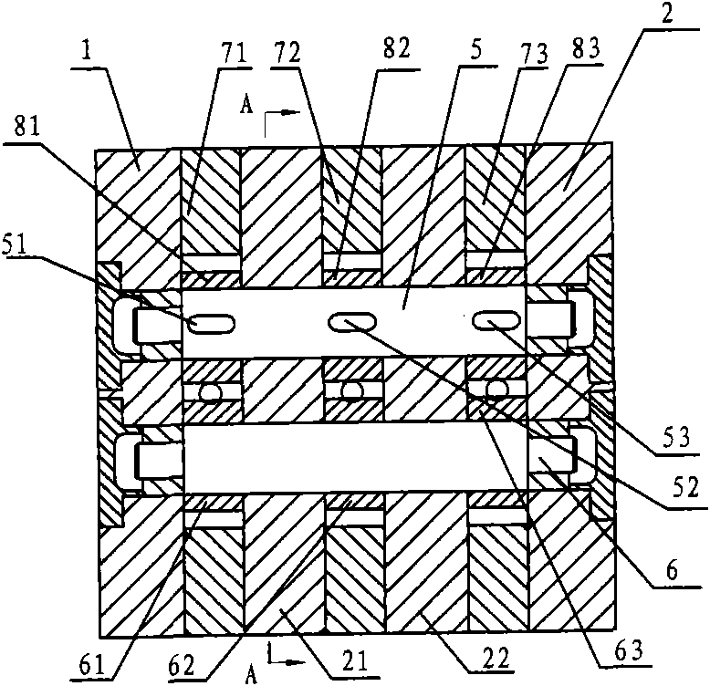
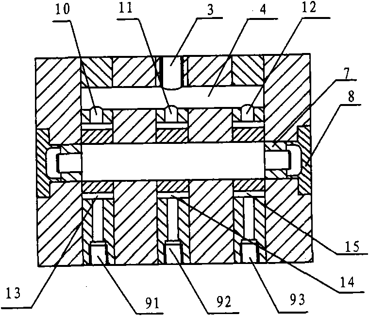
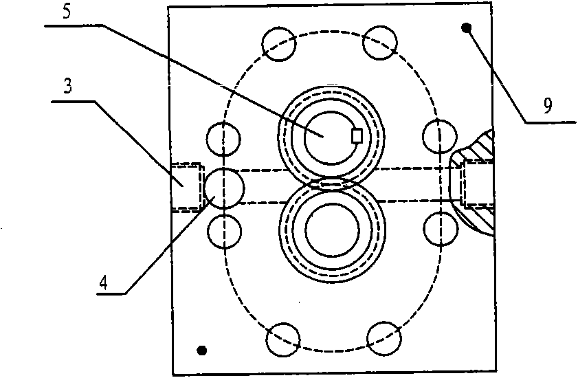
[0013] Such as figure 1 , 2 As shown, the three-axis synchronizing device includes a front end cover 1 and a rear end cover 2, two holes are arranged at the corresponding positions of the front end cover 1 and the rear end cover 2, and sliding bearings 7 are arranged in the holes; the driving shaft 5 and the The two ends of the driven shaft 6 are arranged in the inner holes of the corresponding sliding bearings 7; three oil cavities 71, 72, 73 and two partitions 21, 22 are fixedly arranged between the front end cover 1 and the rear end cover 2 , the separators 21, 22 are set between the three oil chambers 71, 72, 73; the oil inlet 3 is placed on the middle oil chamber 72, and the other end of the oil chamber 71, 72, 73 is provided with an oil outlet Ports 91, 92, 93; on the side close to the oil inlet 3, an oil chamber 4 is arranged parallel to the direction of the driving shaft 5, and the oil chamber 4 runs through all the oil chambers 71, 72, 73 and the partitions 21, 22 an...


PUM


Abstract

The invention provides a tri-spindle synchronizer, which is characterized in that sliding bearings are respectively arranged on positions corresponding to a front end cover and a rear end cover; two ends of a drive shaft and a driven shaft which are arranged in parallel are arranged in the holes of the sliding bearing; three oil cavities and two clapboards are fixedly arranged between the front end cover and the rear end cover, and the clapboard is arranged between the oil cavities; an oil inlet is arranged in the middle oil cavity, and an oil outlet is respectively arranged on the other end of each of the oil cavity; an oil cavity passes through all the oil cavities and the clapboards and is communicated with the oil inlet; three drive wheels are arranged on the drive shaft, three driven wheels which are engaged with the drive wheels correspondingly are arranged on the driven shaft, and one pair of engaged gears are arranged in one oil cavity; and each oil cavity is provided with a high-pressure cavity and a low-pressure cavity.

Description

technical field [0001] The invention relates to a three-spindle synchronization device, in particular to a device for controlling the flow consistency of three oil circuits in a three-spindle hydraulic system. It belongs to the field of machinery manufacturing. Background technique [0002] At present, to complete the synchronous centering movement of the three spindles, manufacturers generally use hydraulic drive. Its structure is that the three main shafts are respectively controlled by independent speed regulating valves to control the equivalent of the oil flow in the oil cylinders of the corresponding main shafts to ensure the centering movement of the three main shafts. Since the three spindles are affected by factors such as resistance, impact or system pressure changes during the movement, the oil distribution will also change accordingly, and the synchronization is difficult to guarantee. Due to many uncertain factors in the hydraulic system itself, coupled with t...

Claims


Application Information

Patent Timeline
Patent Type & Authority Patents(China)
IPC IPC(8): F15B11/22
Inventor 王利民杜锡娟李建华
Owner 山东省青岛生建机械厂
Why Eureka
Try Eureka