Supercharge Your Innovation With Domain-Expert AI Agents!

Decelerator and mounting structure of decelerator to object machine

A technology of reduction gear and installation structure, which is applied in the direction of mechanical equipment, engine seals, engine components, etc., can solve the problems of embedding operation difficulty, wear, and setting size difference, etc., and achieve the effect of simplifying embedding and maintenance and preventing wear

Inactive Publication Date: 2010-06-02
SUMITOMO HEAVY IND LTD
View PDF2 Cites 0 Cited by
  • Summary
  • Abstract
  • Description
  • Claims
  • Application Information

AI Technical Summary

Problems solved by technology

If the dimensional difference is set to be large while prioritizing the ease of fitting, abrasion is more likely to occur
If the dimensional difference is set to be small, it is difficult to cause wear, but the insertion work becomes extremely difficult

Method used


Image

  • Decelerator and mounting structure of decelerator to object machine
  • Decelerator and mounting structure of decelerator to object machine
  • Decelerator and mounting structure of decelerator to object machine

Examples


Embodiment Construction

[0018] Hereinafter, an example of an embodiment of the present invention will be described in detail with reference to the drawings.

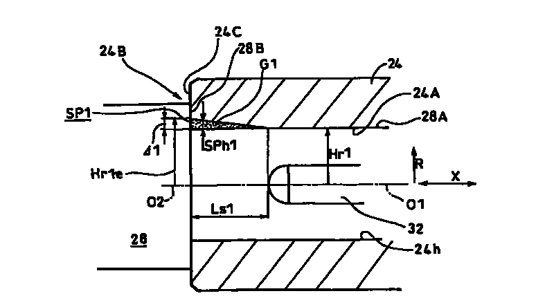
[0019] figure 1 It is a partial schematic plan cross-sectional view showing an example of a geared motor (reduction gear) to which an embodiment of the present invention is applied. figure 2 It is the enlarged sectional view of the II part.

[0020] This geared motor GM1 is mainly composed of a motor 16 and a speed reducer 18 . The motor 16 includes a motor case 20 , and the speed reducer 18 includes a speed reduction case 22 . A hollow output shaft 24 is rotatably supported by the speed reduction case 22 .

[0021] The output shaft 24 has a through hole 24h into which a driven shaft 28 such as a transmission device (target machine: not shown) is inserted. The power transmission between the output shaft 24 and the driven shaft 28 is performed by "formal engagement" via the key 32 , that is, by a structure that has a clearance and is connec...


PUM


Abstract

The invention provides a decelerator which effectively prevents wearing and simplifies operation of the decelerator to a driven shaft of the object machine during embedding or running; the decelerator (GM1) for driving the driven shaft (28) of the object machine has a through hole (24h) holding the driven shaft (28); the driven shaft (28) has an output shaft (24) capable of delivering its rotation through a key (shaped engagement) (32); and from the end portion (24B) of the output shaft (24) along the output shaft (24), a space portion (SP1) maintaining a grease (G1) is disposed between inner periphery (24A) of the output shaft (24) and outer periphery (28A) of the driven shaft.

Description

[0001] This application claims priority based on Japanese Patent Application No. 2008-262393 filed on October 9, 2008. The entire content of this application is used in this specification by reference. technical field [0002] The present invention relates to a reduction gear and an attachment structure of the reduction gear to an object machine. Background technique [0003] Patent Document 1 discloses a structure in which a hollow output shaft of a reduction gear transmission is directly fitted into a driven shaft of a target machine. In this document, a method using a frictional connection without a gap and a method using a positive engagement with a key are proposed for the connection between the driven shaft and the output shaft. [0004] Patent Document 1: Japanese Patent Laid-Open No. 2001-99177 [0005] However, in the method of coupling the above-mentioned driven shaft and output shaft by frictional coupling, it is necessary to always properly manage the mounting ...

Claims


Application Information

Patent Timeline
Patent Type & Authority Applications(China)
IPC IPC(8): F16D1/02F16D1/08F16H57/02F16H57/04F16J15/32F16J15/3268
CPCF16D1/104F16D2300/06
Inventor 河野功
Owner SUMITOMO HEAVY IND LTD
Features
  • R&D
  • Intellectual Property
  • Life Sciences
  • Materials
  • Tech Scout
  • Unparalleled Data Quality
  • Higher Quality Content
  • 60% Fewer Hallucinations
Learn More