Large-angle LED illuminating device

A technology of LED lighting and large angle, applied in the field of lighting, can solve the problems of small light-emitting angle and complex structure of the light source, and achieve the effect of increasing the angle of the LED light source, uniform light-emitting, and convenient production and installation

Inactive Publication Date: 2010-06-02
CIVILIGHT SHENZHEN SEMICON LIGHTING
View PDF0 Cites 12 Cited by
  • Summary
  • Abstract
  • Description
  • Claims
  • Application Information

AI Technical Summary

Problems solved by technology

[0007] In order to solve the technical problems of small light emitting angle and complex structure of the existing light sources, the present invention provides a large-angle LED lighting device with uniform light emission and large irradiation angle

Method used


Image

  • Large-angle LED illuminating device
  • Large-angle LED illuminating device
  • Large-angle LED illuminating device

Examples


Embodiment Construction

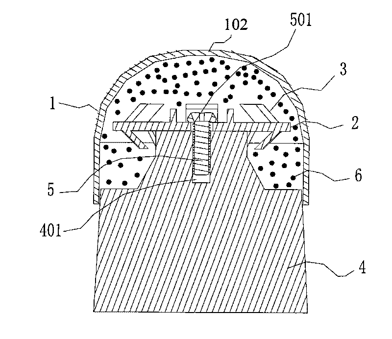
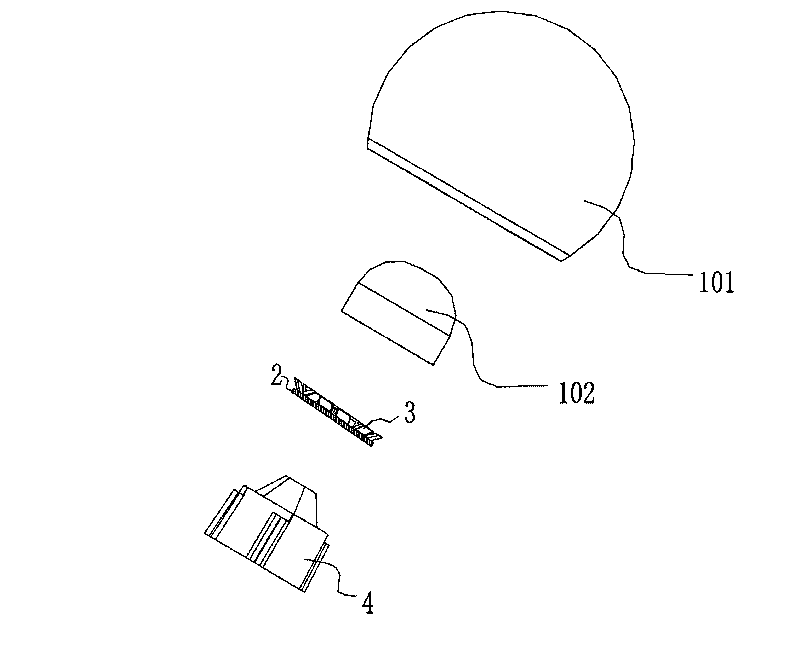
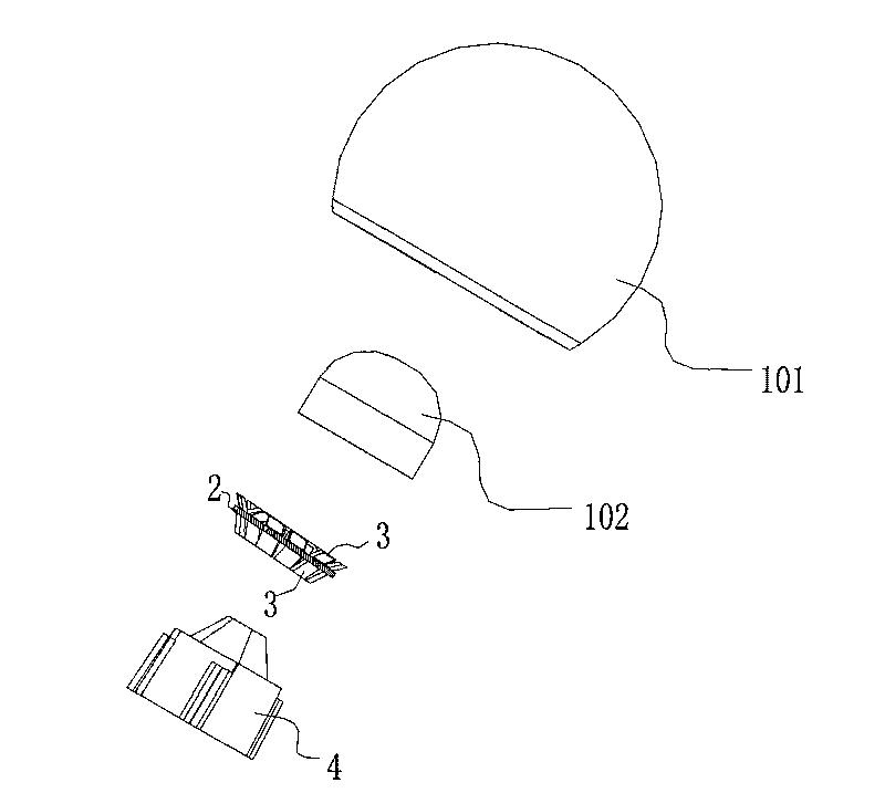
[0033] see Figure 1 - Figure 1 4. The large-angle LED lighting device provided by the present invention is composed of a lampshade 1, a printed circuit board 2, an LED lamp 3 and a heat dissipation column 4. The lampshade 1 includes an outer cover 101 and a diffuser cover 102 for fixing the silicone light diffusion, and the printed circuit board 2 Welded together with the LED lights 3; the LED lights 3 are arranged in a circular array with the center point of the printed circuit board 2 as the center; the LED lights 3 are welded to the upper and lower surfaces of the printed circuit board 2; or welded to the printed circuit board 2 On the upper surface or the lower surface; the angle between the LED lamp 3 and the printed circuit board 2 is 30-90 degrees; preferably 30 degrees or 45 degrees or 60 degrees or 90 degrees. By arranging different angles and arrangement schemes of the LED lamps 3, the angle of the overall LED light source is increased, so that the LED lamps emit li...


PUM


Abstract

The invention provides a large-angle LED illuminating device, which consists of a lampshade, a printed circuit board, LED lamps and a heat dissipation column, wherein the lampshade comprises an outer cover and a diffuser; the printed circuit board is welded with the LED lamps into a whole; the LED lamps are distributed in an annular array by taking the centre of a circle of the printed circuit board as a center; the LED lamps are welded on the upper surface and the lower surface of the printed circuit board or welded on the upper surface or the lower surface of the printed circuit board; the heat dissipation column is fixedly or movably connected with the printed circuit board; and angles of the LED lamps and the printed circuit board are between 20 and 170 DEG. Maximum irradiation angle of light is expanded to 290 DEG by different angles and arrangement scheme of the LED lamps on a light source board so as to achieve the effects of increasing the whole LED light source angle and uniformly illuminating. The device solves the technical problems of small illumination angle and complicated structure of the prior light source, and is simple in production technology and convenient to assemble.

Description

technical field [0001] The invention relates to the lighting field, in particular to a large-angle LED lighting device. Background technique [0002] The existing LED light bulb is limited by the angle, heat dissipation and production process of the LED light-emitting diode itself, and because the light-emitting angle of the LED light bulb is small, the back of the LED light bulb has no light or is very weak. The angle is generally in the range of 130-170°, which limits the application of LED bulbs to a small range. Existing high-power LED bulbs also have the following technical problems: [0003] 1) The light-emitting angle of the LED light-emitting diode is small, which limits the light-emitting angle of the entire light source; [0004] 2) The luminous flux of the LED bulb is low; [0005] 3) Due to the use of multiple LEDs to form light spots on the outside of the product, it is difficult to handle; [0006] 4) The color rendering index of LED bulbs is low. Due to t...

Claims


Application Information

Patent Timeline
Patent Type & Authority Applications(China)
IPC IPC(8): F21S2/00F21V19/00F21V29/00F21Y101/02
CPCF21Y2105/005Y10S362/80F21Y2101/02F21K9/00F21V19/0055F21V3/04F21V19/001F21K9/60F21Y2107/50F21Y2107/90F21Y2115/10
Inventor 薛信燊林丕达
Owner CIVILIGHT SHENZHEN SEMICON LIGHTING
Why Eureka
Try Eureka