Condensing range hood

A range hood, condensing technology, applied in the field of range hoods, can solve problems such as polluting the environment, high temperature of the oil fume mixture, and reducing the service life of the range hood

Inactive Publication Date: 2010-06-02
广东顾家电器有限公司
View PDF0 Cites 20 Cited by
  • Summary
  • Abstract
  • Description
  • Claims
  • Application Information

AI Technical Summary

Problems solved by technology

The problems of the above technologies are: the temperature of the oil fume mixture entering the separation net is high, it is difficult to separate in the separation net, and the discharged gas still contains a large number of mist molecules, which not only pollutes the environment, but also accumulates oil on the impeller of the fan for a long time , and enter the inside of the motor, causing the impeller to lose its dynamic balance, greatly affecting the wind force and reducing the service life of the range hood

Method used


Image

  • Condensing range hood
  • Condensing range hood
  • Condensing range hood

Examples


Embodiment 1

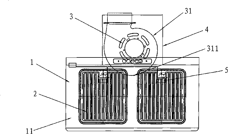
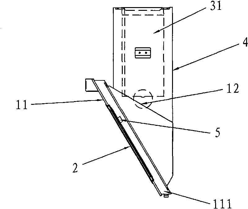
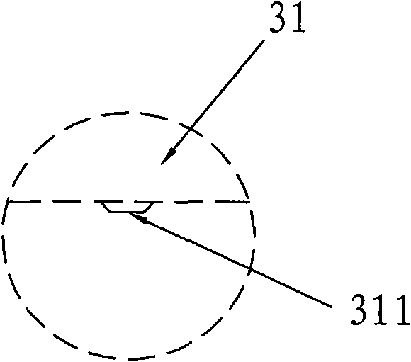
[0020] Such as figure 1 , figure 2 As shown, a condensing range hood includes a housing 1, a separation net 2, a centrifugal fan 3 and a control device. The housing 1 is composed of a front panel 11, two side panels, a rear panel and a top panel 12. The separation net 2 is set On the air inlet of the front panel 11, there is an oil collecting tank 11 at the bottom of the front panel 11; diagram 2-1 As shown, there is an oil drip hole 311 on the centrifugal fan housing 31; a coaming plate 4 is arranged on the top plate 12, and the centrifugal fan 3 is installed in the coaming plate 4;

[0021] Described refrigerating device is made of semiconductor refrigeration sheet 5;

[0022] The semiconductor cooling plate 5 is arranged on the separation net 2 and is located on the inner surface of the separation net 2 .

Embodiment 2

[0024] Such as image 3 , Figure 4 as shown,

[0025] A semiconductor cooling plate 5 is arranged in the centrifugal fan casing 31, above the oil drip hole 311, and the cooling surface is opposite to the oil drip hole.

[0026] As a further improvement of this embodiment, another semiconductor cooling plate 5 is arranged on the surface of the separation net 2 in the casing, and the cooling surface is opposite to the separation net 2 .

Embodiment 3

[0028] Such as Figure 5 , Figure 6 As shown, the refrigerating device is composed of a semiconductor cooling plate 5 and a cooling tube 6, the cooling tube 6 is bent into a fence shape, and the fence-shaped part 61 of the cooling tube 6 is bonded to the separation net 2; One end of the tube 5 cooperates with the cooling surface of the semiconductor cooling plate 5 , and the other end is open; the heating surface of the semiconductor cooling plate 5 communicates with the outside of the housing 1 .

[0029] A further improvement of this embodiment is that the open end of the cooling pipe 6 extends into the centrifugal fan casing 31 from the oil drip hole 311 of the centrifugal fan casing 31 .


PUM


Abstract

The invention discloses a condensing range hood, which comprises a shell, a separation screen, a centrifugal fan and a control device, wherein the shell consists of a front panel, two lateral plates, a rear plate and a top plate, the separation screen is arranged on the air inlet of the front panel and the bottom part of the front panel is provided with an oil collecting groove; the housing of the centrifugal fan is provided with oil holes; and a surrounding plate is arranged on the top plate, and the centrifugal fan is arranged in the surrounding plate. The condensing range hood is characterized by comprising a refrigerating device which is arranged in the shell. Due to the adopted structure, an oil and fume mixed gas entering the separation screen is cooled to a lower temperature, so that when the oil fume passes through the separation screen, oil is condensed and drops into the oil groove at the bottom part of the front panel and then flows into the oil collecting oil. Thus, the oil and fume separation rate is improved effectively and environmental pollution is reduced greatly.

Description

technical field [0001] The invention relates to a range hood. Background technique [0002] In the current existing technology, a range hood includes a housing, a separation net, a centrifugal fan and a control device. The housing is composed of a front panel, two side panels, a rear panel and a top panel. The oil tank at the bottom has an oil discharge port, and the oil discharge port is located above the oil collection tank; a coaming plate is arranged on the top plate, and the centrifugal fan is installed in the coaming plate. The problems of the above technologies are: the temperature of the oil fume mixture entering the separation network is high, it is difficult to separate in the separation network, and the discharged gas still contains a large number of mist molecules, which not only pollutes the environment, but also accumulates oil on the impeller of the fan for a long time , and enter the inside of the motor, causing the impeller to lose its dynamic balance, whic...

Claims


Application Information

Patent Timeline
Patent Type & Authority Applications(China)
IPC IPC(8): F24C15/20
Inventor 陈艺强
Owner 广东顾家电器有限公司
Why Eureka
Try Eureka