Multi-beam deformation detecting device and use method thereof
A detection device and multi-beam technology, applied in the direction of measuring devices, optical devices, instruments, etc., can solve problems such as real-time prevention and accurate detection of obstacles in bridge detection, long-term online monitoring of bridge deflection, great influence of weather changes and air turbulence, etc. , to achieve the effect of long-term online monitoring, accurate deformation and simple structure
- Summary
- Abstract
- Description
- Claims
- Application Information
AI Technical Summary
Problems solved by technology
Method used
Image
Examples
Embodiment 1
[0033] Embodiment 1, applying the multi-beam deformation detection device provided by the present invention to bridge deformation detection:
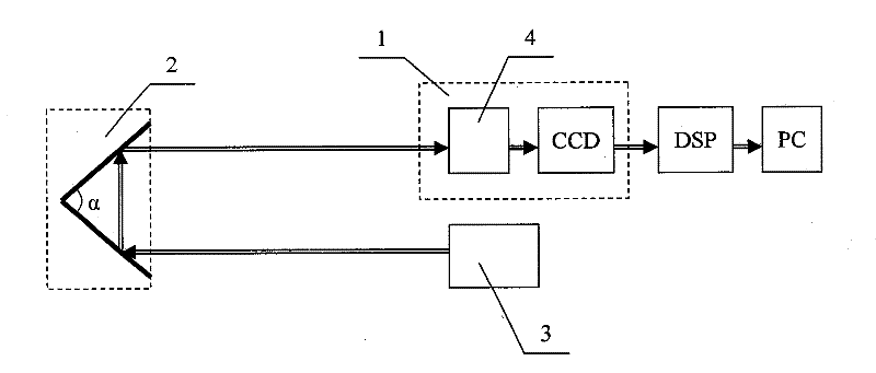
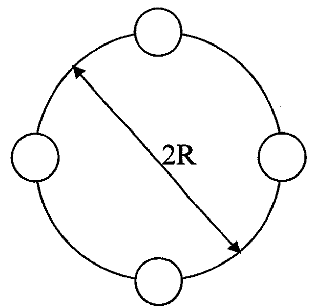
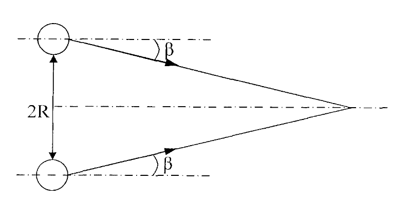
[0034] Such as figure 1 As shown, the multi-beam deformation detection device is composed of a detector 1, a prism reflecting target 2 and a laser group 3. The detector 1 and the laser group 3 are installed on the shore, and the prism reflecting target 2 is installed under the main girder of the bridge. Surface, the angle α between the two reflective surfaces of the prism reflective target 2 = 64°. The laser beam group emitted by the laser group 3 is reflected by the first prism surface of the prism reflection target 2 to the second prism surface of the prism reflection target 2, and after being reflected by the second prism surface, it is received by the optical antenna 4 and sent to the photoelectric image sensor CCD. An overlapping light spot is formed on the camera, and the digital signal processor DSP takes out the information of ...
Embodiment 2
[0044] Embodiment 2, the multi-beam deformation detection device provided by the present invention is applied to landslide detection: a prism reflection target 2 is installed on the top of the mountain to be measured, a detector 1 and a laser group 3 are installed at the measurement point, and the laser light emitted by the laser group 3 After the beam group is reflected by the prism reflection target 2, overlapping spots are formed on the detector 1, and the centroid of the overlapping spots is determined by the photoelectric tracking macropixel iterative centroid method. After 3-6 months or more, after deformation interference occurs at the point to be measured, the moving distance H of the centroid of the overlapping light spots is obtained to determine the deformation of the point to be measured on the mountain, and then determine the deformation of the mountain. If the mountain body undergoes major changes, corresponding landslide prevention measures should be taken.
[0...
PUM
 Abstract
Description
Claims
Application Information
 - R&D
- Intellectual Property
- Life Sciences
- Materials
- Tech Scout
- Unparalleled Data Quality
- Higher Quality Content
- 60% Fewer Hallucinations
Browse by: Latest US Patents, China's latest patents, Technical Efficacy Thesaurus, Application Domain, Technology Topic, Popular Technical Reports.
© 2025 PatSnap. All rights reserved.Legal|Privacy policy|Modern Slavery Act Transparency Statement|Sitemap|About US| Contact US: help@patsnap.com


