Method for measuring ferroelectric hysteresis loop of leakage ferroelectric film

A technology of ferroelectric thin film and hysteresis loop, applied in the direction of measuring current/voltage, measuring electrical variables, measuring devices, etc., can solve the problems of deepening the difficulty of thin film electrical measurement, unclear understanding of people, and increase of quantum tunneling current

Active Publication Date: 2012-01-18
FUDAN UNIV
View PDF0 Cites 6 Cited by
  • Summary
  • Abstract
  • Description
  • Claims
  • Application Information

AI Technical Summary

Problems solved by technology

However, when the thickness of the film is close to or lower than the critical dimension, the flipping mechanism must be different. The understanding of the mechanism is still unclear, which affects the further development of device functions.
In addition, as the film thickness decreases, the quantum tunneling current increases correspondingly
On the one hand, this tunneling current will change with the reorientation of the electrical domain, which can be applied to the non-destructive reading of logic signals in high-density FRAM memory cells, which is of positive significance; on the other hand, it also further improves Leakage current is reduced, which deepens the difficulty of thin film electrical measurement
That is, even if we were able to grow flawless thin-film crystals, it would be impossible to complete the electrical characterization of these films using existing commercial equipment

Method used


Image

  • Method for measuring ferroelectric hysteresis loop of leakage ferroelectric film
  • Method for measuring ferroelectric hysteresis loop of leakage ferroelectric film
  • Method for measuring ferroelectric hysteresis loop of leakage ferroelectric film

Examples


Embodiment Construction

[0026] The pulse signals required for the test are all edited by Agilent 81150A arbitrary waveform signal generator, the current is recorded by LCWR6200A oscilloscope, and the internal resistance of the system is 50 ohms.

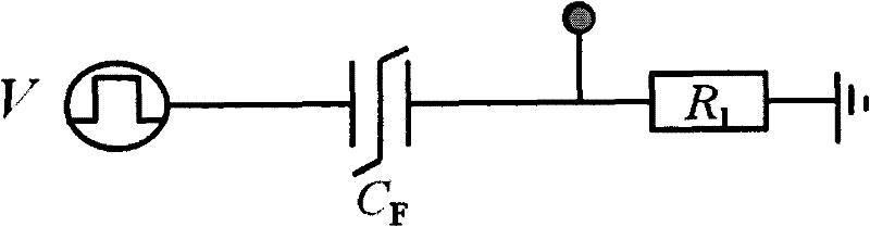
[0027] Measure a simulated leakage ferroelectric thin film system consisting of a standard ferroelectric capacitor and resistor in parallel.

[0028] (1) Use a pulse generator to first generate a pulse with a sufficient width so that the reversible electric domain in the measured leakage ferroelectric film is completely reversed under the applied voltage.

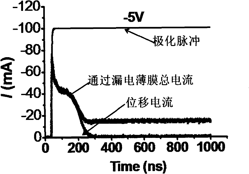
[0029] (2) After the current is stable, measure the current passing through the ferroelectric film with the same polarity as the leakage current. Since the polarization direction of the ferroelectric domain is consistent with the direction of the external electric field at this time, the measurement process is carried out after the capacitor is fully charged, and the measured current only includes the lea...


PUM


Abstract

The invention belongs to the technical field of solid dielectric performance testing, and in particular discloses a method for measuring a ferroelectric hysteresis loop of a leakage ferroelectric film. The method of the invention comprises the following steps: firstly, applying external voltages of the same polarity onto the polarized leakage ferroelectric film, testing and recording the leakage currents at the two ends of the film passing through the ferroelectric film under the different voltages and performing curve fitting to obtain a functional equation of the leakage currents and the applied voltages; performing calculation to obtain the change relationships of polarization currents of reversed electric domains and time; finally integrating the displacement currents with respect to the time to calculate the density of displacement charges generated by the ferroelectric film under the applied voltages; and repeating the measurement and calculation processes to obtain electric displacement corresponding to the ferroelectric film under the different voltage so as to measure the ferroelectric hysteresis loop of the whole leakage ferroelectric film. The method has the advantages of overcoming the difficulty in the electric characteristics of the leakage ferroelectric film and specifically providing powerful means for study on the electric characteristics of the ultra-thin leakage ferroelectric film.

Description

technical field [0001] The invention belongs to the technical field of solid-state dielectric performance testing, and in particular relates to a testing method for a hysteresis loop of a leakage ferroelectric film. Background technique [0002] Ferroelectric thin film materials have high spontaneous polarization and large dielectric constant and can be applied to non-volatile random access memory (FRAM), dynamic random access memory (DRAM), uncooled infrared detectors, thin film dielectric capacitors , microwave devices modulated by electric field, AC electroluminescent devices and thin film sensors, etc. With the improvement of device integration density, the device unit size has been greatly reduced, approaching the atomic or molecular level. It is expected that the storage density of FRAM and DRAM in the future can reach ~Tb / in 2 The order of magnitude is close to the level of magnetic recording hard disks currently manufactured using vertical technology. [0003] The ...

Claims


Application Information

Patent Timeline
IPC IPC(8): G01R19/00
Inventor 江安全刘骁兵
Owner FUDAN UNIV
Why Eureka
Try Eureka