Permanent-magnet self-starting synchronous motor

A synchronous motor, self-starting technology, applied in the direction of magnetic circuit rotating parts, magnetic circuit shape/style/structure, etc., can solve the problems of permanent magnets not being able to enter, high processing technology requirements, and asymmetric magnetic circuit structure, etc. To achieve the effect of simple structure, large magnetic flux, and convenient processing

Active Publication Date: 2010-06-02
东元总合科技(杭州)有限公司
View PDF0 Cites 3 Cited by
  • Summary
  • Abstract
  • Description
  • Claims
  • Application Information

AI Technical Summary

Problems solved by technology

like Figure 1 to Figure 4 As shown, the rotor of a general permanent magnet self-starting motor usually adopts a straight, V-shaped, U-shaped or W-shaped permanent magnet. The permanent magnet structure used is completely determined by the amount of permanent magnets required in the motor design. The above Various structures need to deal with the relationship between the permanent magnet slot and the rotor slot to meet the strength of the ...

Method used


Image

  • Permanent-magnet self-starting synchronous motor
  • Permanent-magnet self-starting synchronous motor
  • Permanent-magnet self-starting synchronous motor

Examples


Embodiment 1

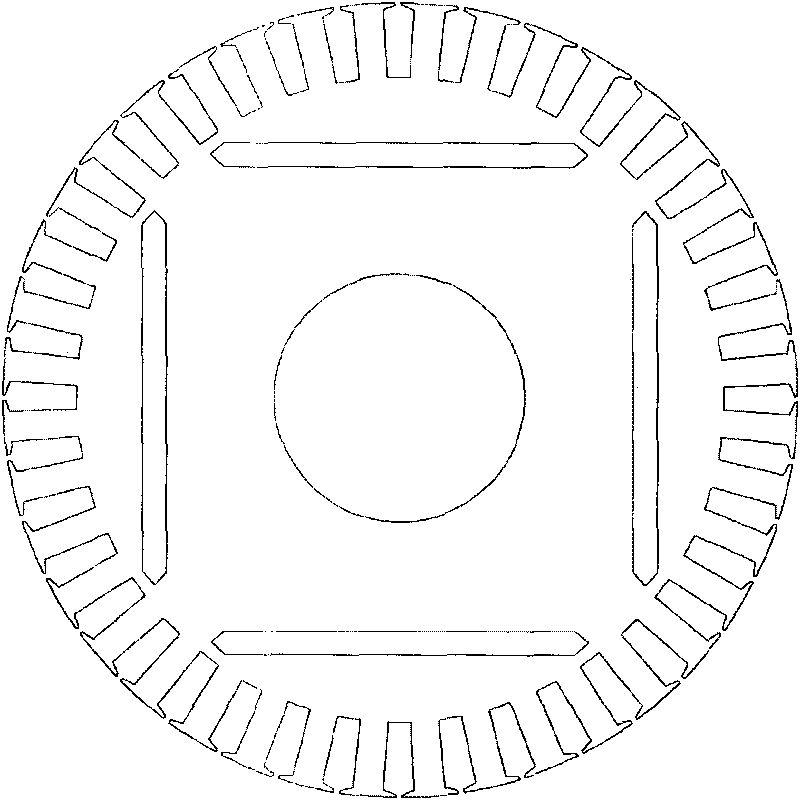
[0038] The permanent magnet self-starting synchronous motor refers to a permanent magnet motor with a starting winding on the rotor, which can start itself and pull in synchronous operation at a certain voltage and frequency. During the starting process, the rotor conductor generates a starting electromagnetic torque. When running synchronously, The rotor conductors do not work. Therefore, the circumference of the rotor is provided with rotor slots for winding the starting winding, and the part between two adjacent rotor slots constitutes rotor teeth, and the rotor slots and rotor teeth are arranged at intervals. Generally, the rotor of a low-power permanent magnet self-starting synchronous motor is made of cast aluminum, and the rotor slot adopts a trapezoidal slot structure. Opposite to the rotor trapezoidal slot is a rotor tooth with a rectangular tooth structure, which is mainly to ensure the uniformity of the magnetic circuit; The rotor of the high-power permanent magnet ...

Embodiment 2

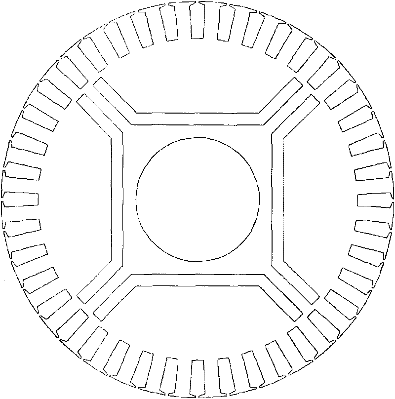
[0052] see Figure 7 , the other structure of this embodiment is the same as that of Embodiment 1, the difference is that: the rotor is divided into 4 pole areas by the centerlines 23, 24, 25, 26 of the rotor slots, and the adjacent pole areas are separated by the center line of the rotor slots. is the boundary, and the centerline of the rotor slot refers to the line passing through the center of the rotor circle and the center of any rotor slot. This embodiment also only takes the rotor with 4 poles as an example, and is not limited to be applicable only to the case of the rotor with 4 poles, and is also applicable to the case of the rotor with 6 poles or 8 poles.


PUM


Abstract

The invention provides a permanent-magnet self-starting synchronous motor which has the advantages that a rotor permanent magnet has simple structure and high permanent-magnet utilization, and a magnetic field formed in the motor has minimum change. The motor comprises a rotor, and rotor teeth and rotor slots are arranged on the circumference of the rotor. The rotor is equally divided into polar areas with the same number of rotor poles by a rotor tooth center line passing through the circle center of the rotor, wherein circular-arc permanent magnets are arranged in each polar area, and permanent magnets in any two adjacent polar areas are arranged symmetrically by a rotor tooth center line at the boundary of the adjacent polar areas. By the circular-arc permanent magnets and rotor iron cores at the bottom of the rotor slots, magnetic separation can be realized without singly building a magnetic separation bridge, and by adjusting the distance between the bottom of the rotor slots and the permanent magnets, magnetic leakage coefficient among poles can be adjusted. The rotor slots not only have the function of magnetic separation, but also have the function of synchronization starting and introducing.

Description

technical field [0001] The invention relates to the technical field of permanent magnet motors, in particular to a permanent magnet self-starting synchronous motor. Background technique [0002] IEC60034-3 points out that industrial motors in the world consume 30-40% of the total power generation, and its system optimization energy-saving potential can reach 30-60%. Save 7% of electric energy worldwide, of which 1 / 4 to 1 / 3 of the savings can come from improving the efficiency of the motor. [0003] According to statistics, in 2007, high-efficiency motors sold in China's domestic market accounted for about 1% of the total sales of motors. More than 98% of the motor products are ordinary efficiency motors, which are 3% lower than the efficiency of high-efficiency motors in the United States and 5% lower than the efficiency of ultra-high-efficiency motors; the efficiency of fans, pumps, and compressors is 3-5 percentage points lower than foreign advanced levels; There is a la...

Claims


Application Information

Patent Timeline
IPC IPC(8): H02K1/27
Inventor 刘立军
Owner 东元总合科技(杭州)有限公司
Why Eureka
Try Eureka