
Free forging method of forge piece of rotary arms

A technology for forgings and swivel arms, which is applied in the field of free forging of swivel arm forgings, can solve the problems of increased production resource consumption, difficult to repair, and large forging allowances, so as to reduce the cost of forgings, ensure internal quality, and reduce forgings. The effect of weight

Inactive Publication Date: 2010-06-09
MCC SFRE HEAVY IND EQUIP
View PDF1 Cites 20 Cited by
  • Summary
  • Abstract
  • Description
  • Claims
  • Application Information

AI Technical Summary

Problems solved by technology

This type of forging requires more additional forging blocks during production, and the eccentricity between the large circle and the small circle is not easy to control, and the required forging allowance is also larger than that of ordinary forgings, resulting in an increase in the weight of the forgings
In the forging production process, due to the large diameter and height of the disc, it is very difficult to control the quality of forgings, and due to the limitation of the shape of forgings, it is not easy to repair by forging after quality problems occur
If die forging is used, although the margin can be reduced and the weight of forgings can be reduced, die forging equipment with greater forging capacity needs to be selected, not only the production of high-precision forging dies, but also the consumption of other various production resources is also significantly increased

Method used


Image

  • Free forging method of forge piece of rotary arms
  • Free forging method of forge piece of rotary arms
  • Free forging method of forge piece of rotary arms

Examples


Embodiment Construction

[0027] The present invention will be described in detail below in conjunction with the accompanying drawings and specific embodiments.

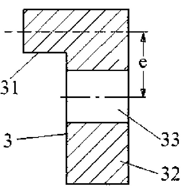
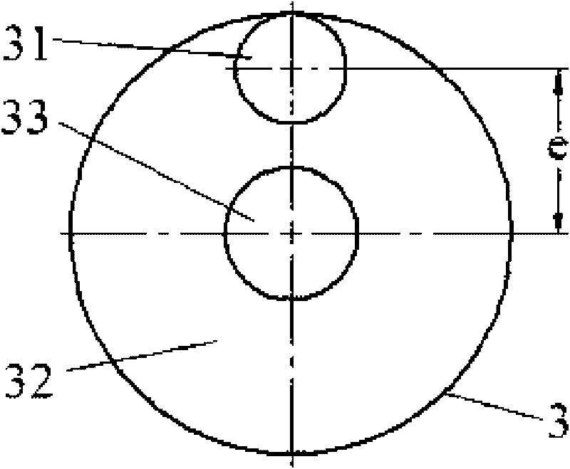
[0028] like figure 1 , 2 As shown, it is a structural schematic diagram of the forging of the arm type used by the method of the present invention. The structure of the forging 3 is to include a forging inner hole 33 on the axis of the large disk 32, an eccentric cylinder 31 is arranged at the eccentric position of the axis of the large disk 32, and the axis of the eccentric cylinder 31 is aligned with the forging inner hole. The distance between the axes of 33 is e.

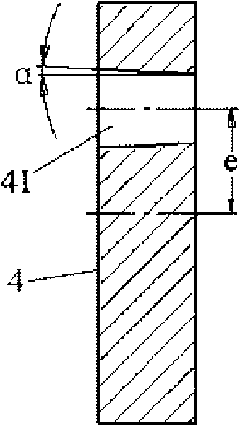
[0029] like image 3 , 4 As shown, it is a schematic view of the tire mold structure that adopts the method of the present invention to use. The tire mold hole 41 is eccentrically arranged on the tire mold 4, and the distance between the axis line of the tire mold hole 41 and the axis line of the tire mold 4 is e, The inner hole of the tire mold hole 41 is a conical surfac...


PUM


Abstract

The invention discloses a free forging method of a forge piece of rotary arms, which comprises the steps of: firstly, making a forming die and an upsetting punch; secondly, first forging: heating a steel ingot, tapping and pressing a clamp handle, and removing the clamp handle to obtain desirable blank material of the forge piece; thirdly, second forging: putting a rotary upsetting table on a movable work table, putting the forming die on the rotary upsetting table, putting the desirable blank material of the forge piece into the forming die, putting the upsetting punch at the upper end face of one large circle of the blank material of the forge piece, and forging; and horizontally moving the movable work table to achieve the aim of performing; fourthly, third forging: installing a flat anvil on the end face of the large circle of the blank material of the forge piece, further widening, rolling to be a circle, and furnace filling; and fifthly, fourth forging: overturning the upper surface and the lower surface of the blank material of the forge piece, flatting the other large circle of the blank material of the forge piece, punching, rolling to be a circle, and finishing with many times to obtain a finished product of the forge piece of the rotary arms. The method has simple steps, and guarantees the forging quality.

Description

technical field [0001] The invention belongs to the technical field of forging, and is used for forging a rotary arm type forging on a forging hydraulic press with a movable workbench, and in particular relates to a free forging method for a rotary arm type forging. Background technique [0002] In the free forging production, the shape of the forging parts of the rotating arm is relatively special. Its structural feature is that there is an eccentric cylinder near the rim of the disc with a large diameter. This type of forging requires more additional forging blocks during production, and the eccentricity between the large circle and the small circle is not easy to control, and the required forging allowance is also larger than that of ordinary forgings, resulting in an increase in the weight of the forging. In the forging production process, due to the large diameter and height of the disc, it is very difficult to control the quality of the forging, and due to the limitati...

Claims


Application Information

Patent Timeline
IPC IPC(8): B21J5/02B21J5/08
Inventor 张皓晔马建平孙来来彭忠
Owner MCC SFRE HEAVY IND EQUIP
Learn More