Lathe tool-changing mechanism on compound processing machine tool of mill lathe
A tool changing mechanism and compound processing technology, which is applied in the direction of metal processing machinery parts, metal processing equipment, manufacturing tools, etc., can solve the problem that automatic clamping and tool changing of turning tools cannot be realized, and the production efficiency of milling and turning compound processing machines can be reduced. Affect the automation degree of milling and turning machine tools and other issues, and achieve the effect of improving the way of angle positioning control
- Summary
- Abstract
- Description
- Claims
- Application Information
AI Technical Summary
Problems solved by technology
Method used
Image
Examples
specific Embodiment approach 1
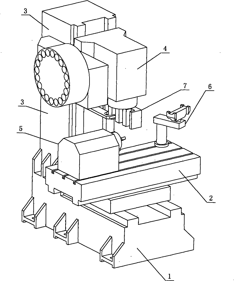
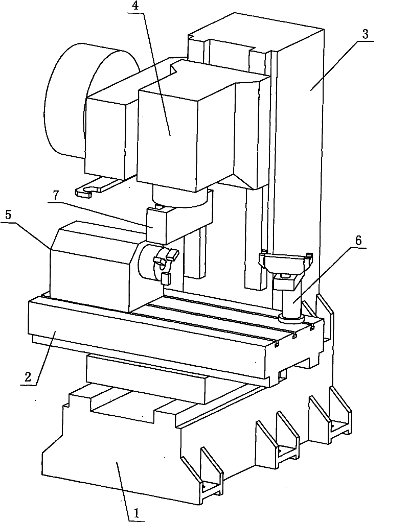
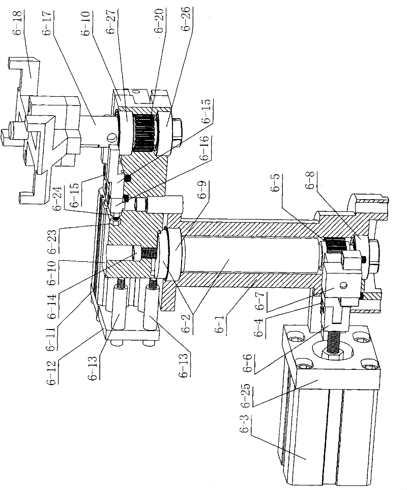
[0009] Specific implementation mode one: as Figure 1-8 As shown, the lathe tool changing mechanism 6 on the milling and turning compound processing machine tool described in this embodiment includes a shaft sleeve 6-1, a main transmission shaft 6-2, a first cylinder 6-3, a first rack 6-4, First gear 6-5, first rack positioner 6-7, first bearing 6-8, second bearing 6-9, rocker arm 6-10, second cylinder 6-11, rocker arm positioning connector 6 -14, two adjustment blocks 6-15, positioning block 6-16, rotating body 6-17, tool holder 6-18, second rack 6-19, second gear 6-20, second rack positioning Device 6-22, two adjusting screws 6-23, two positioning nuts 6-24, the third bearing 6-26, the fourth bearing 6-27 and positioning shaft 6-28; the main transmission shaft 6-2 is installed on the shaft In the cover 6-1, the first bearing 6-8 is housed between the lower end of the main transmission shaft 6-2 and the shaft sleeve 6-1, and the first bearing 6-8 is housed between the upper ...
specific Embodiment approach 2
[0010] Specific implementation mode two: as image 3 and Figure 4 As shown, the lathe tool change mechanism 6 in this embodiment also includes a fork-shaped connecting piece 6-6 and a first cylinder connecting plate 6-25, and the piston connecting rod of the first cylinder 6-3 passes through the fork-shaped connecting piece 6-6. It is connected with the first rack 6-4, and the first cylinder 6-3 is connected with the lower end side wall of the shaft sleeve 6-1 through the first cylinder connecting plate 6-25. Such arrangement makes the structure more compact and facilitates assembly. Other components and connections are the same as those in the first embodiment.
specific Embodiment approach 3
[0011] Specific implementation mode three: as image 3 and Figure 4 As shown, the lathe tool changing mechanism 6 in this embodiment also includes a second cylinder connecting plate 6-12, a second cylinder connecting plate connecting piece 6-13 and a second rack connecting plate 6-21, and the second cylinder connecting plate 6-12 is connected with the rocker arm 6-10 through the second cylinder connection plate connector 6-13, and the second cylinder 6-11 is installed on the second cylinder connection plate 6-12. Such arrangement makes the structure more compact and facilitates assembly. Other compositions and connections are the same as those in Embodiment 1 or 2.
PUM
 Abstract
Description
Claims
Application Information
 - R&D
- Intellectual Property
- Life Sciences
- Materials
- Tech Scout
- Unparalleled Data Quality
- Higher Quality Content
- 60% Fewer Hallucinations
Browse by: Latest US Patents, China's latest patents, Technical Efficacy Thesaurus, Application Domain, Technology Topic, Popular Technical Reports.
© 2025 PatSnap. All rights reserved.Legal|Privacy policy|Modern Slavery Act Transparency Statement|Sitemap|About US| Contact US: help@patsnap.com


