Planet speed reduction driving mechanism

A transmission mechanism and planetary deceleration technology, applied in transmission devices, mechanical equipment, ceramic molding machines, etc., can solve the problems of rising production costs of extruders, backward configuration of reducers, and complicated structure of extruders, so as to save power consumption. , The speed ratio range is expanded, and the energy saving effect is remarkable.

Inactive Publication Date: 2012-06-13
程玉全
View PDF0 Cites 0 Cited by
  • Summary
  • Abstract
  • Description
  • Claims
  • Application Information

AI Technical Summary

Problems solved by technology

The reason: In addition to factors such as metal materials, production equipment and processing methods, there are obvious differences in the design and configuration of the reduction transmission mechanism. The intuitive manifestations are: First, the configuration of the reducer is backward, and most manufacturers still use The traditional ZQ series reducer is used, but with the transformation of industrial policies, brick-making raw materials (change from high plastic clay to hard plastic extrusion) and product performance (thin-walled high-strength, high-cavity, self-insulation), the extruder’s The specifications, models and power are getting bigger and bigger, which makes the model of the reducer bigger and bigger, so that there is no match
Second, large-scale ZQ series reducers are large in size, heavy in weight, small in speed ratio, and low in efficiency. For example, a 60-type hard plastic vacuum extruder with a power greater than 250KW needs to be equipped with a 130-type reducer. The weight of the reducer itself is 7500kg, the volume (length, width, height) is 2500×1100×1526 (mm), and the average market price is 150,000 yuan. Its weight, volume and price all account for 1 / 3 of the entire extruder, resulting in extrusion The production cost of the machine is rising
The third is that the ZQ series reducer is a general-purpose product for the society, not specially designed for the extruder of brick and tile forming. more improved

Method used


Image

  • Planet speed reduction driving mechanism
  • Planet speed reduction driving mechanism
  • Planet speed reduction driving mechanism

Examples


Embodiment Construction

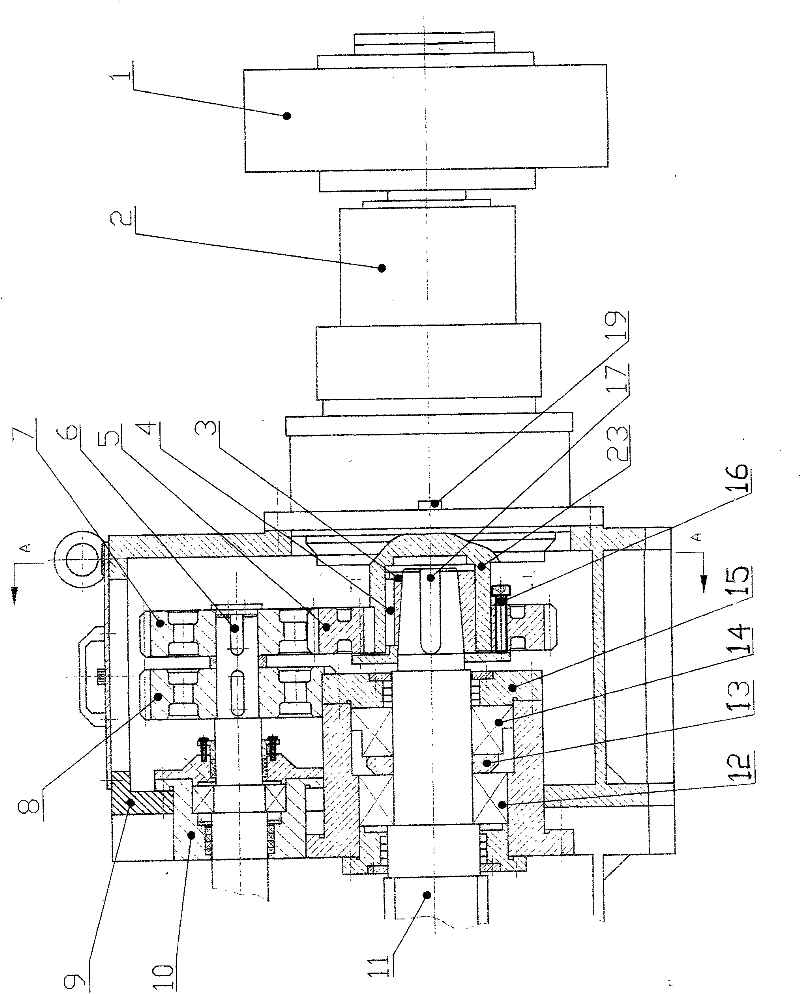
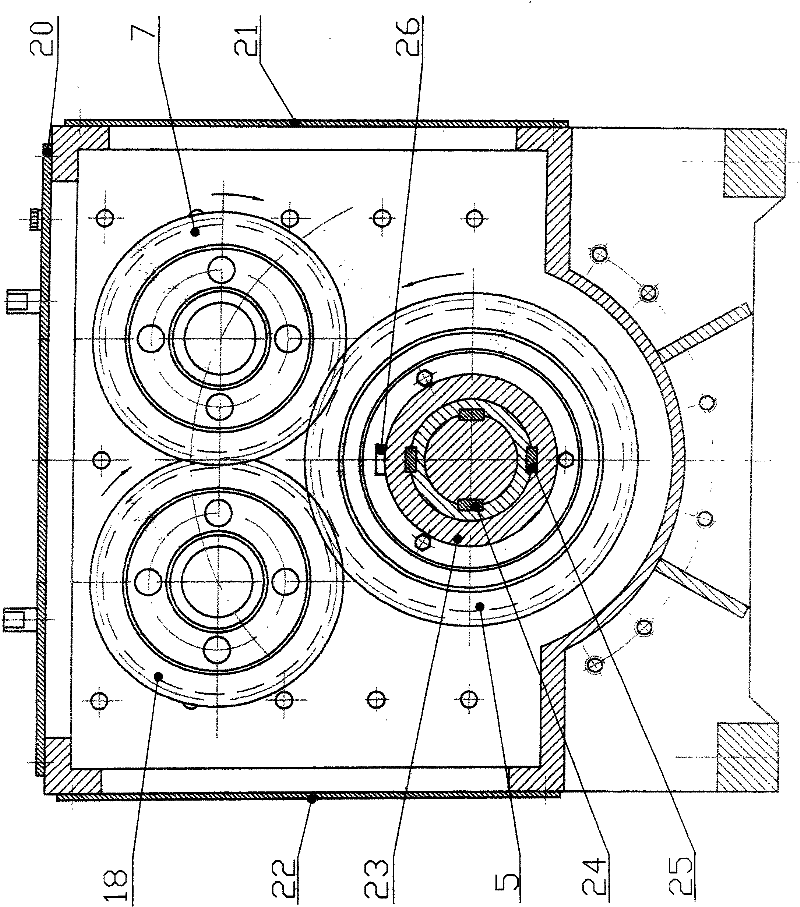
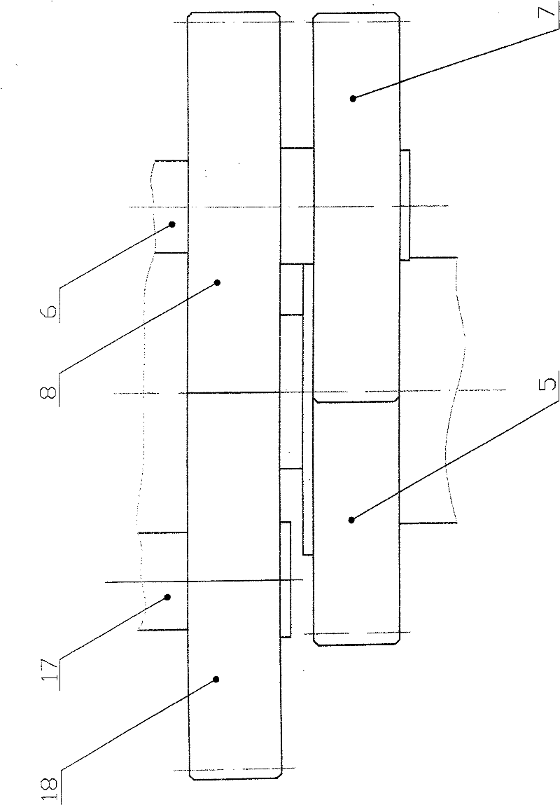
[0019] The planetary reduction transmission mechanism of the present invention mainly includes a pneumatic clutch 1, a planetary reducer 2, a transmission gearbox 9, a plurality of transmission gears, and a tensioning taper sleeve 3 and other components. The pneumatic clutch 1 is installed on the power input shaft of the planetary reducer 2, and the output shaft of the planetary reducer 2 is directly inserted into the joint hole behind the gear transmission box 9, and its fixed flange and the rear end surface of the joint hole are connected by 32 bolts 19 fixed. The driving gear 5 is installed on the output shaft of the planetary reducer 2, the driven gear 7 is installed on the upper right mud pressing shaft 6, and meshes with the driving gear, and the pair of gears 8 and the driven gear 7 are installed coaxially and on the same step, and are installed on the The pair of gears 18 on the mud pressing shaft 17 on the upper left are horizontally meshed. The extrusion shaft 11 is...


PUM


Abstract

The invention relates to a planet speed reduction driving mechanism, which comprises a pneumatic clutch, a planet speed reducer, a drive gear box and a plurality of transmission gears, wherein the pneumatic clutch is arranged on a power input shaft of the planet speed reducer; an output shaft of the planet speed reducer is directly inserted in a combination hole behind the drive gear box, and a mounting flange on the output shaft is connected and fixed with the rear end face of the combination hole by a bolt; a driving gear in the transmission gears is arranged on the output shaft of the planet speed reducer; a driven gear in the transmission gears is arranged on an upper right mud-pressing shaft and is meshed with the driving gear; a counter gear in the transmission shaft are arranged with the driven shaft on the same step coaxially and is horizontally meshed with a counter gear arranged on an upper left mud-pressing shaft; and an extrusion shaft is directly inserted in an inner hole of the output shaft of the planet speed reducer and is fixed with the inner hole by a tension cone sleeve for power transmission. The planet speed reduction driving mechanism adopts a straight-tooth cylindrical gear set to drive the two mud-pressing shafts, the straight-tooth cylindrical gear set is operated harmoniously with the extrusion shaft, the driving gear is directly arranged on the output shaft of the speed reducer, the driven gear and the counter gears are arranged at two mud-pressing shaft ends, and three sets of shaft couplings are saved, so the transmission efficiency and the transmission accuracy are improved.

Description

technical field [0001] The invention belongs to the technical field of mechanical transmission devices, in particular to a deceleration transmission mechanism for large vacuum extruders in the field of brick and tile machinery manufacturing. Background technique [0002] With the deepening of the reform of wall materials in our country, the brick and tile industry has begun to develop towards large-scale, intensified and automated aspects. New requirements have become the primary issue facing the brick and tile machinery manufacturing industry. It is true that in recent years, brick and tile equipment manufacturing enterprises have invested a lot of effort and sweat to provide the industry with many new models with large specifications and high pressure. However, compared with similar foreign products in terms of their comprehensive technical level, there is still a large gap, especially It is an extruder used in the brick and tile forming process. No matter its volume, wei...

Claims


Application Information

Patent Timeline
Patent Type & Authority Patents(China)
IPC IPC(8): F16H37/06B28B3/20
Inventor 程玉全刘志忠汝永琪
Owner 程玉全
Why Eureka
Try Eureka