Continuous vacuum coating method and special equipment thereof
A technology of vacuum coating and special equipment, applied in the fields of vacuum coating method and equipment, continuous coating method and equipment, can solve the problems of poor stability, working efficiency coating process uniformity and stability, low production efficiency, etc. The effect of small redundancy, simple and reliable equipment composition, and high production efficiency
- Summary
- Abstract
- Description
- Claims
- Application Information
AI Technical Summary
Problems solved by technology
Method used
Image
Examples
Embodiment 1
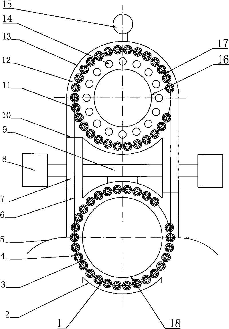
[0022] Such as figure 1 As shown, the special equipment of the present invention comprises a pre-pumping chamber 3 and a coating chamber 12 adjacently arranged, a vacuum valve lock 10 is provided between the two, and a low vacuum is respectively provided outside the pre-pumping chamber 3 and the coating chamber 12 Unit 8 and High Vacuum Unit 15. Described coating chamber 12 is the annular structure that is made of vacuum outer wall 13 and vacuum inner wall 16, is provided with annular interlocking turret track 17 in this annular coating chamber 12, is equipped with on this annular interlocking turret track 17 and is equipped with One or more than one sputtering targets or other evaporation sources 14 are arranged beside the circular linkage turret track 17 on the linkage turret 11 for clamping workpieces.
[0023] Described pre-pumping chamber 3 is ring-shaped structure, and each two ends of this annular pre-pumping chamber 3 are connected with described coating chamber 12 th...
Embodiment 2
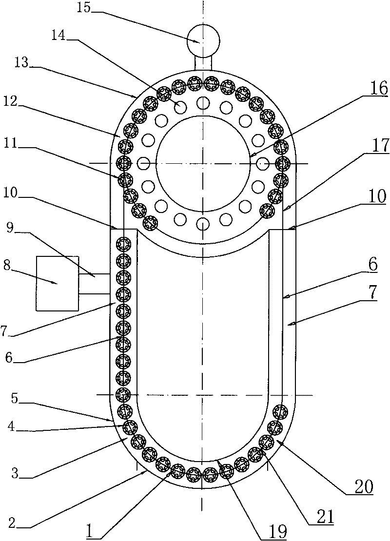
[0027] Such as image 3 As shown, the difference between this embodiment and Embodiment 1 is that the pre-pumping chamber 3 is composed of a U-shaped vacuum inner wall 19 and a vacuum outer wall 2 to form a U-shaped vacuum tunnel. In this U-shaped pre-pumping chamber 3 Described linear turret track 6 is housed in the vacuum tunnel 7 of the linear part, and semicircular interlocking turret track 21 is housed in the inside of the semicircular vacuum chamber 20 at the lower end of the U-shaped pre-pumping chamber 3 .
[0028] In this embodiment, a semicircular vacuum chamber structure is used to realize the function of the pre-pumping chamber, and the conversion between the pre-pumping chamber 3 and the coating chamber 12 is realized by using it in combination with a vacuum tunnel. The advantage is that the structure is simpler.
Embodiment 3
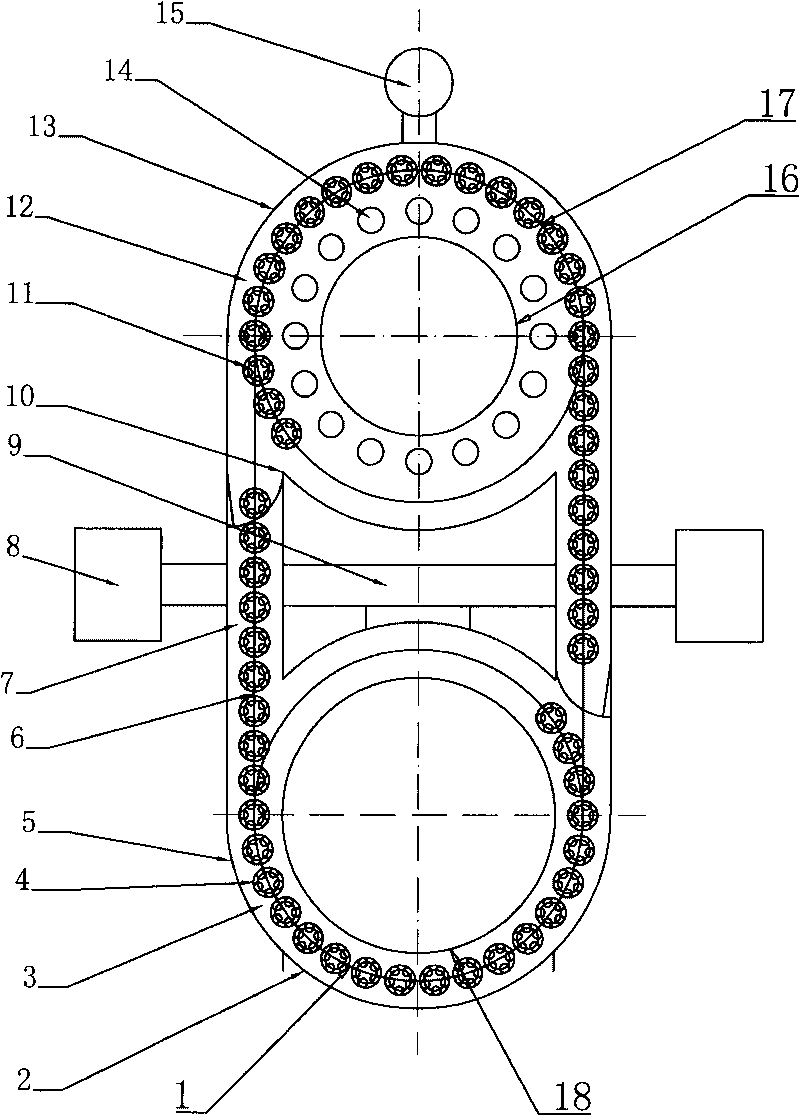
[0030] Such as Figure 4As shown, the difference between this embodiment and embodiment 1 is that the annular pre-pumping chamber 3 and two vacuum tunnels 7 in embodiment 1 are merged into a large vacuum chamber, while retaining the pre-pumping chamber 3 of embodiment 1 The characteristic of the circular track is that the structure is simple.
[0031] The working process of the above-mentioned embodiment 2 and embodiment 3 is basically the same as that of the embodiment 1, and will not be repeated here.
[0032] The present invention arranges vacuum valve lock 10 at the connection vacuum tunnel 7 of two vacuum chambers (pre-pumping chamber 3 and coating chamber 12), opens vacuum valve lock 10 and then Unicom pre-pumping chamber 3 and coating chamber 12, through vacuum tunnel 7 will The workpieces to be plated in the pre-pumping chamber 3 are transferred to the coating chamber 12, and the coated workpieces in the coating chamber 12 are transferred to the pre-pumping chamber 3 ...
PUM
 Abstract
Description
Claims
Application Information
 - R&D
- Intellectual Property
- Life Sciences
- Materials
- Tech Scout
- Unparalleled Data Quality
- Higher Quality Content
- 60% Fewer Hallucinations
Browse by: Latest US Patents, China's latest patents, Technical Efficacy Thesaurus, Application Domain, Technology Topic, Popular Technical Reports.
© 2025 PatSnap. All rights reserved.Legal|Privacy policy|Modern Slavery Act Transparency Statement|Sitemap|About US| Contact US: help@patsnap.com


