Continuous vacuum coating method and special equipment thereof

A technology of vacuum coating and special equipment, applied in the field of continuous coating method and equipment, vacuum coating method and equipment, can solve the problems of poor stability, working efficiency coating process uniformity and stability, low production efficiency, etc. The effect of small redundancy, simple and reliable equipment composition, and high production efficiency

Active Publication Date: 2012-11-14
BEIJING TUS CLEAN ENERGY TECH CO LTD
View PDF1 Cites 0 Cited by
  • Summary
  • Abstract
  • Description
  • Claims
  • Application Information

AI Technical Summary

Problems solved by technology

[0003] The purpose of the present invention is to provide a double-chamber solar collector tube vacuum coating system and its continuous coating method, to solve the problem that the existing single vacuum chamber coating method has to be exposed to the atmosphere every time the coating is completed. After the pre-plated workpiece is installed on the top, the vacuum degree of the vacuum chamber is evacuated to the background vacuum, resulting in low production efficiency, poor quality stability of each batch of products, and the problem that the efficiency of the equipment is greatly affected in the rainy summer season; and multi-vacuum The structure of continuous chamber coating equipment is complex, the difficulty of control and maintenance is greatly increased, the equipment investment is high, the stability is poor, and too many switches between vacuum chambers cause the redundant time of coating time to be too long, resulting in a decrease in production efficiency, and The linear movement linkage bracket makes the work efficiency of the sputtering target and the uniformity and stability of the coating process worse

Method used


Image

  • Continuous vacuum coating method and special equipment thereof
  • Continuous vacuum coating method and special equipment thereof
  • Continuous vacuum coating method and special equipment thereof

Examples


Embodiment 1

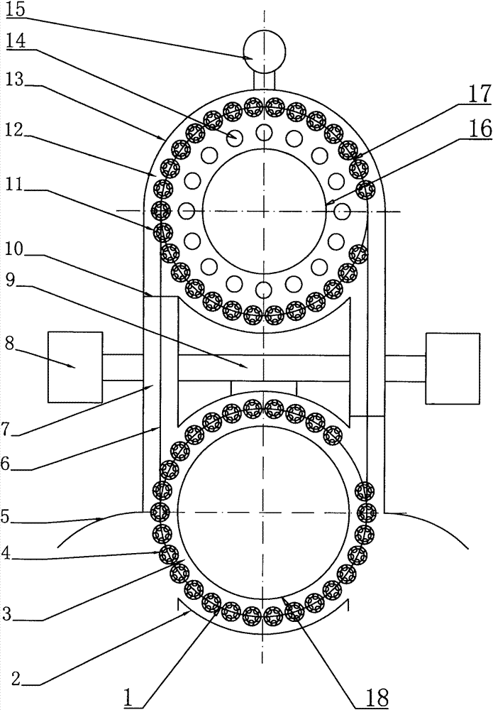
[0022] Such as figure 1 As shown, the special equipment of the present invention comprises a pre-pumping chamber 3 and a coating chamber 12 adjacently arranged, a vacuum valve lock 10 is provided between the two, and a low vacuum is respectively provided outside the pre-pumping chamber 3 and the coating chamber 12 Unit 8 and High Vacuum Unit 15. Described coating chamber 12 is the annular structure that is made of vacuum outer wall 13 and vacuum inner wall 16, is provided with annular interlocking turret track 17 in this annular coating chamber 12, is equipped with on this annular interlocking turret track 17 and is equipped with One or more than one sputtering targets or other evaporation sources 14 are arranged beside the circular linkage turret track 17 on the linkage turret 11 for clamping workpieces.

[0023] Described pre-pumping chamber 3 is ring-shaped structure, and each two ends of this annular pre-pumping chamber 3 are connected with described coating chamber 12 th...

Embodiment 2

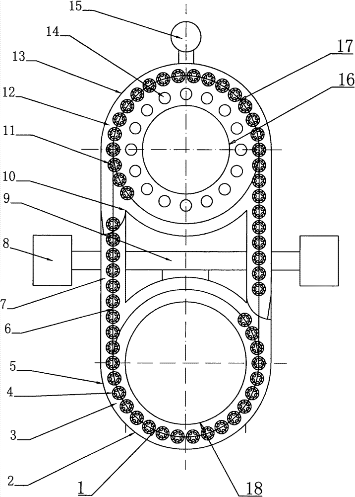
[0027] Such as image 3 As shown, the difference between this embodiment and Embodiment 1 is that the pre-pumping chamber 3 is composed of a U-shaped vacuum inner wall 19 and a vacuum outer wall 2 to form a U-shaped vacuum tunnel. In this U-shaped pre-pumping chamber 3 Described linear turret track 6 is housed in the vacuum tunnel 7 of the linear part, and semicircular interlocking turret track 21 is housed in the inside of the semicircular vacuum chamber 20 at the lower end of the U-shaped pre-pumping chamber 3 .

[0028] In this embodiment, a semicircular vacuum chamber structure is used to realize the function of the pre-pumping chamber, and the conversion between the pre-pumping chamber 3 and the coating chamber 12 is realized by using it in combination with a vacuum tunnel. The advantage is that the structure is simpler.

Embodiment 3

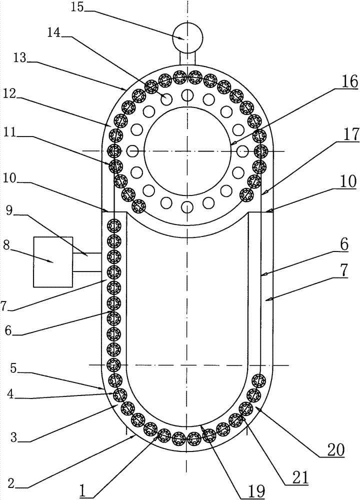
[0030] Such as Figure 4As shown, the difference between this embodiment and embodiment 1 is that the annular pre-pumping chamber 3 and two vacuum tunnels 7 in embodiment 1 are merged into a large vacuum chamber, while retaining the pre-pumping chamber 3 of embodiment 1 The characteristic of the circular track is that the structure is simple.

[0031] The working process of the above-mentioned embodiment 2 and embodiment 3 is basically the same as that of the embodiment 1, and will not be repeated here.

[0032] The present invention arranges vacuum valve lock 10 at the connection vacuum tunnel 7 of two vacuum chambers (pre-pumping chamber 3 and coating chamber 12), opens vacuum valve lock 10 and then Unicom pre-pumping chamber 3 and coating chamber 12, through vacuum tunnel 7 will The workpieces to be plated in the pre-pumping chamber 3 are transferred to the coating chamber 12, and the coated workpieces in the coating chamber 12 are transferred to the pre-pumping chamber 3 ...


PUM


Abstract

The invention relates to a continuous vacuum coating method and special equipment thereof, wherein the method comprises the following steps of: firstly installing workpieces on an annular linked rotating frame in a pre-vacuum chamber and pre-vacuuming; then leading a first batch of workpieces into a coating chamber adjacent to the pre-vacuum chamber through the annular linked rotating frame, subsequently closing a vacuum valve lock between the pre-vacuum chamber and the coating chamber and carrying out vacuum coating for the first batch of workpieces; meanwhile, installing a second batch of workpieces into the pre-vacuum chamber and pre-vacuuming; and afterwards, leading out the first batch of coated workpieces from the coating chamber, simultaneously leading the second batch of workpieces into the coating chamber to carry out a coating working procedure and simultaneously taking out the coated workpieces whenever a new batch of workpieces are installed to realize continuous coating. The continuous vacuum coating method and the special equipment thereof have the advantages that a continuous coating process is realized by adopting a double vacuum chamber coating system, the equipment has simple and reliable components and small redundancy, and two vacuum chambers can realize full load operation and have high production efficiency.

Description

technical field [0001] The invention relates to a vacuum coating method and equipment, in particular to a continuous coating method and equipment suitable for preparing a coating on the surface of a tubular workpiece, belonging to the technical field of vacuum coating. Background technique [0002] Vacuum coating technology is the core technology in the manufacturing process of all-glass vacuum solar collector tubes. With the development of solar thermal utilization technology, vacuum coating equipment and technology for the preparation of selective absorption coatings for all-glass vacuum solar collector tubes have also been continuously improved. development of. Single vacuum chamber single sputtering target, single vacuum chamber multi-sputtering target and multi-vacuum chamber multi-sputtering target coating equipment and coating process have appeared successively. For the single-vacuum chamber coating system, its defect is that: every time a coating is completed, the v...

Claims


Application Information

Patent Timeline
Patent Type & Authority Patents(China)
IPC IPC(8): C23C14/56
Inventor 韩成明李旭光王青山孙海中
Owner BEIJING TUS CLEAN ENERGY TECH CO LTD
Why Eureka
Try Eureka