Supercharge Your Innovation With Domain-Expert AI Agents!

Comb teeth type hydraulic three-dimensional garage

A three-dimensional garage and comb-tooth technology, which is applied in the direction of parking buildings, building types, buildings, etc., can solve the problems of restricting large-scale hydraulic lifts, high production costs, and failure to break through the lifting height

Inactive Publication Date: 2010-06-09
李祥启
View PDF0 Cites 12 Cited by
  • Summary
  • Abstract
  • Description
  • Claims
  • Application Information

AI Technical Summary

Problems solved by technology

Although the hydraulic three-dimensional parking equipment has the above advantages, there are also some technical problems that need to be solved. For example, the common hydraulic three-dimensional garage is to install the hydraulic lifter horizontally on the traversing frame of each floor, and use the hydraulic lifter to Push the rope to drive the vehicle-carrying plate vertically up and down, and move the traversing frame horizontally through the driving mechanism to achieve horizontal movement. Since the length of the hydraulic lift cylinder corresponds to the lifting range, the size of the main frame of the three-dimensional parking equipment limits the large The use of hydraulic lifts, therefore, ordinary hydraulic three-dimensional parking equipment can only be used for structures with 2-3 floors
In addition, since the hydraulic lifter on the traversing frame not only needs to push the rope up and down, but also needs to move horizontally by itself, the structure is complicated, the production cost is high, and the limit of the lifting height cannot be broken.

Method used


Image

  • Comb teeth type hydraulic three-dimensional garage
  • Comb teeth type hydraulic three-dimensional garage
  • Comb teeth type hydraulic three-dimensional garage

Examples


Embodiment Construction

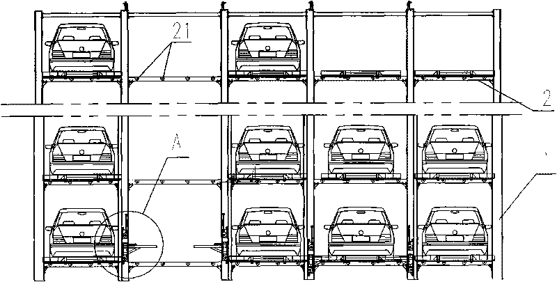
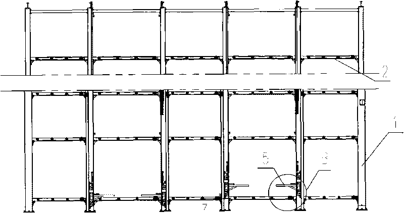
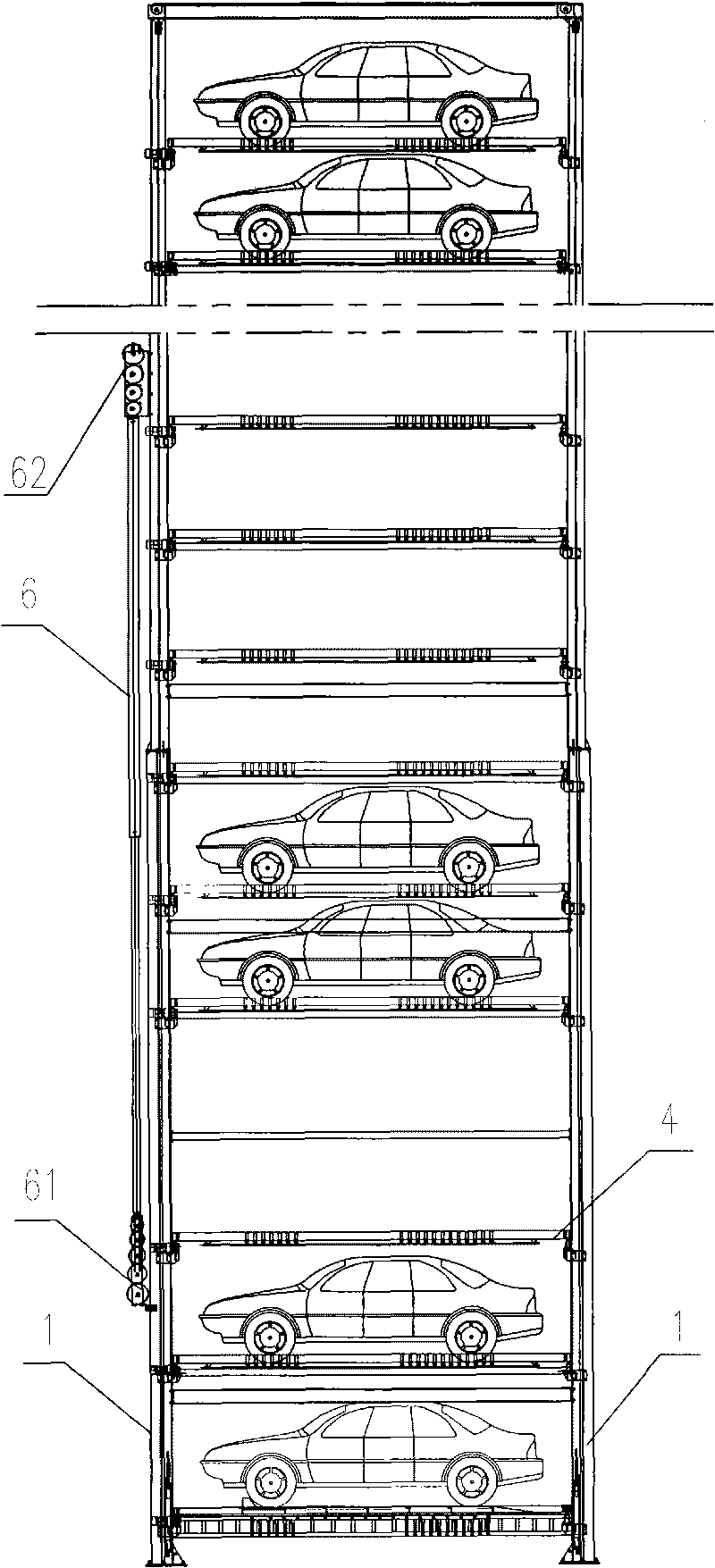
[0017] Such as figure 1 -- image 3 As shown, the comb-teeth type hydraulic three-dimensional garage of the present invention includes a column 1, a crossbeam 2, and a longitudinal beam that constitute the main frame. The column 1 adopts U-shaped channel steel or H-shaped channel steel and is vertically arranged. The groove on the column 1 Can be used as a chute. The beams 2 and the longitudinal beams are perpendicular to each other and arranged horizontally to form the garage level, and the multiple vertical columns 1 arranged in parallel divide the main frame into multiple columns, and the multiple garage levels arranged in parallel divide the main frame into multiple floors. The crossbeam 2 on the first floor is equipped with driving roller 21, and driving roller 21 is through the combination of chain, sprocket wheel, or the combination of belt, belt pulley and traversing drive motor 22 transmission connections, and traversing drive motor 22 is fixedly installed on the mai...


PUM


Abstract

The invention relates to a comb teeth type hydraulic three-dimensional garage which comprises upright posts, transverse beams and longitudinal beams which are forming a main framework. A plurality of parallel upright posts divide the main framework into a plurality of longitudinal rows, and a plurality of parallel garage bedding surfaces divide the main framework into a plurality of floors, wherein transmission rollers are arranged on the transverse beams of each floor, and comb teeth traversing plates are put in the transmission rollers; at least one longitudinal row is provided with a comb teeth frame comprising a bracket and a comb teeth rod; both ends of the comb teeth frame are arranged in slide grooves on the upright posts and connected to a lifting rope, and the lifting rope is connected with a lifting mechanism; the comb teeth rods are horizontally arranged, and the outer ends of the comb teeth rods are fixedly connected to the brackets; and each longitudinal row provided with the comb teeth frame is symmetrically provided with two pairs comb frames with a symmetrical structure left and right. The comb teeth type hydraulic three-dimensional garage cancels a carrying plate capable of being lifted, thereby greatly simplifying the structure of moving parts and being beneficial to reducing the production cost and improving the reliability. In addition, a longitudinally arranged hydraulic lifting jack is not limited by the length any more and can be used for a super high-rise three-dimensional garage.

Description

technical field [0001] The invention relates to a three-dimensional parking device, in particular to a comb-teeth hydraulic three-dimensional garage. technical background [0002] Most of the existing three-dimensional parking equipment adopts the lifting method of the motor-driven sling, but the disadvantages of the motor-driven are obvious. First, the noise of the motor-driven is large, and the operation is not stable enough. The speed cannot be increased, especially for high-rise three-dimensional parking equipment, the time for taking and storing the car is long, which affects the efficiency of use; again, there is no dead point in the operation of the motor, once the protective measures are wrong, it is easy to cause accidents such as roof fall and car crash The reliability of the protective measures will in turn lead to an increase in manufacturing costs. The hydraulic three-dimensional parking equipment can well solve the above problems, and the hydraulic lifter runs...

Claims


Application Information

Patent Timeline
Patent Type & Authority Applications(China)
IPC IPC(8): E04H6/18
Inventor 李祥啟刘影李仁业
Owner 李祥启
Features
  • R&D
  • Intellectual Property
  • Life Sciences
  • Materials
  • Tech Scout
  • Unparalleled Data Quality
  • Higher Quality Content
  • 60% Fewer Hallucinations
Learn More